Features:
- Expanded Pin Count: 54 digital I/O pins and 16 analog inputs, allowing connection and control of many devices and components.
- Increased Memory: 256 KB Flash memory, four times that of standard Arduino boards, enabling complex programs and larger data storage.
- Greater Processing Power: ATmega2560 microcontroller running at 16 MHz for faster instruction execution.
- Enhanced Serial Communication: Multiple UART interfaces for simultaneous communication with multiple devices.
- Support for Advanced Communication Protocols: SPI and I2C support for seamless integration with sensors, displays, and memory chips.
- Robust Development Environment: The user-friendly Arduino IDE for writing, compiling, and uploading code.
- Onboard Serial Converter and Bootloader: Allows programming without an external programmer.
- Extensive Library Support: Vast collection of libraries to simplify interfacing with sensors and modules.
Description:
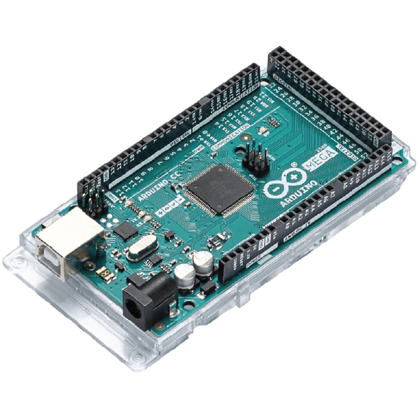
The Arduino Mega 2560 is ideal for projects demanding a large number of pins — with 70 IO pins compared to Arduino UNO's 20. This abundance of pins supports complex and expansive projects such as robotics, automation, data logging, and more. It retains all Arduino ecosystem advantages, including compatibility with many shields and modules, extensive documentation, and a friendly programming environment.
Principle of Work:
Arduino offers an open hardware and software ecosystem, allowing free use and modification of its designs and software. The Arduino IDE enables writing and uploading sketches easily. The board includes onboard Serial Converter and bootloader to simplify programming. Libraries provide pre-written functions for common tasks, making development faster and simpler.
How the Arduino Mega Works:
- Power Supply: Powered via USB or external supply (7-12V recommended).
- Microcontroller: ATmega2560 executes instructions and manages peripherals.
- Digital and Analog Pins: Used for reading sensors or controlling devices.
- Programming: Done via Arduino IDE with sketches written in C/C++.
- Sketches: Consist of
setup()andloop()functions. - Libraries: Simplify interaction with hardware modules.
- Communication: Supports Serial, I2C, SPI protocols.
- Expansion: Compatible with shields and modules to extend functionality.
Pinout of the Module:

Power Supply
Can be powered through USB or external supply (AC-DC adapters or batteries). Recommended voltage is 7 to 12 volts.
Pin Details:
- Digital Pins: 54 digital pins (0-53) configurable as input or output.
- Analog Pins: 16 analog input pins (0-15), can also be used as digital pins.
- PWM Pins: Pins 2-13 support PWM via
analogWrite(). - USART Pins: Pins 0-1, 14-19 used for serial communication.
- SPI Pins: Pins 22-25 for SPI communication.
- I2C Pins: Pins 20 (SDA) and 21 (SCL) for I2C communication.
- Hardware Interrupt Pins: Digital pins 2,3,18-21.
- AREF Pin: Reference voltage for analog inputs.
- Reset Pin: Resets the microcontroller.
Applications:
- Robotics: Control multiple motors, sensors, and actuators.
- Home Automation: Control appliances, lighting, security, and sensors.
- Data Acquisition: Interface with various sensors for logging and analysis.
- Instrumentation and Control Systems: Custom control panels and monitoring.
- Educational Projects: Teaching electronics, programming, and robotics.
- Prototyping: Rapid testing and development of ideas.
- Art and Interactive Installations: Control dynamic interactive artworks.
- Automation and Industrial Control: Interface with industrial sensors and actuators.
Circuit
No additional circuit needed for the example below; it uses the built-in LED on pin 13.
Connecting Arduino for the First Time:
- Open Arduino IDE. Download it from Arduino IDE Download.
- Connect board to computer using a data USB cable.
- Select the board in Tools > Board.
- Select the port in Tools > Port.
- Upload a sketch like "Blink" from File > Examples > 01.Basics > Blink.
Troubleshooting:
If your board doesn't appear in the port menu, refer to Arduino Troubleshooting Guide.
Example Code: Blink LED with Serial Monitor Status
// Blink Example with LED Status in Serial Monitor
const int LED_PIN = 13;
void setup() {
 pinMode(LED_PIN, OUTPUT);
 Serial.begin(9600);
 Serial.println("Blink Example with LED Status");
}
void loop() {
 digitalWrite(LED_PIN, !digitalRead(LED_PIN));
 Serial.print("LED Status: ");
 Serial.println(digitalRead(LED_PIN));
 delay(1000);
}
Code Explanation:
const int LED_PIN = 13;defines the LED pin.setup()initializes the LED pin as output and starts serial communication.loop()toggles the LED state, prints its status, then waits 1 second.
Technical Details:
- Microcontroller: ATmega2560
- Clock Speed: 16 MHz
- Operating Voltage
Features:
- Expanded Pin Count: 54 digital I/O pins and 16 analog inputs, allowing connection and control of many devices and components.
- Increased Memory: 256 KB Flash memory, four times that of standard Arduino boards, enabling complex programs and larger data storage.
- Greater Processing Power: ATmega2560 microcontroller running at 16 MHz for faster instruction execution.
- Enhanced Serial Communication: Multiple UART interfaces for simultaneous communication with multiple devices.
- Support for Advanced Communication Protocols: SPI and I2C support for seamless integration with sensors, displays, and memory chips.
- Robust Development Environment: The user-friendly Arduino IDE for writing, compiling, and uploading code.
- Onboard Serial Converter and Bootloader: Allows programming without an external programmer.
- Extensive Library Support: Vast collection of libraries to simplify interfacing with sensors and modules.
Description:
The Arduino Mega 2560 is ideal for projects demanding a large number of pins — with 70 IO pins compared to Arduino UNO's 20. This abundance of pins supports complex and expansive projects such as robotics, automation, data logging, and more. It retains all Arduino ecosystem advantages, including compatibility with many shields and modules, extensive documentation, and a friendly programming environment.
Principle of Work:
Arduino offers an open hardware and software ecosystem, allowing free use and modification of its designs and software. The Arduino IDE enables writing and uploading sketches easily. The board includes onboard Serial Converter and bootloader to simplify programming. Libraries provide pre-written functions for common tasks, making development faster and simpler.
How the Arduino Mega Works:
- Power Supply: Powered via USB or external supply (7-12V recommended).
- Microcontroller: ATmega2560 executes instructions and manages peripherals.
- Digital and Analog Pins: Used for reading sensors or controlling devices.
- Programming: Done via Arduino IDE with sketches written in C/C++.
- Sketches: Consist of
setup()andloop()functions. - Libraries: Simplify interaction with hardware modules.
- Communication: Supports Serial, I2C, SPI protocols.
- Expansion: Compatible with shields and modules to extend functionality.
Pinout of the Module:
Power Supply
Can be powered through USB or external supply (AC-DC adapters or batteries). Recommended voltage is 7 to 12 volts.
Pin Details:
- Digital Pins: 54 digital pins (0-53) configurable as input or output.
- Analog Pins: 16 analog input pins (0-15), can also be used as digital pins.
- PWM Pins: Pins 2-13 support PWM via
analogWrite(). - USART Pins: Pins 0-1, 14-19 used for serial communication.
- SPI Pins: Pins 22-25 for SPI communication.
- I2C Pins: Pins 20 (SDA) and 21 (SCL) for I2C communication.
- Hardware Interrupt Pins: Digital pins 2,3,18-21.
- AREF Pin: Reference voltage for analog inputs.
- Reset Pin: Resets the microcontroller.
Applications:
- Robotics: Control multiple motors, sensors, and actuators.
- Home Automation: Control appliances, lighting, security, and sensors.
- Data Acquisition: Interface with various sensors for logging and analysis.
- Instrumentation and Control Systems: Custom control panels and monitoring.
- Educational Projects: Teaching electronics, programming, and robotics.
- Prototyping: Rapid testing and development of ideas.
- Art and Interactive Installations: Control dynamic interactive artworks.
- Automation and Industrial Control: Interface with industrial sensors and actuators.
Circuit
No additional circuit needed for the example below; it uses the built-in LED on pin 13.
Connecting Arduino for the First Time:
- Open Arduino IDE. Download it from Arduino IDE Download.
- Connect board to computer using a data USB cable.
- Select the board in Tools > Board.
- Select the port in Tools > Port.
- Upload a sketch like "Blink" from File > Examples > 01.Basics > Blink.
Troubleshooting:
If your board doesn't appear in the port menu, refer to Arduino Troubleshooting Guide.
Example Code: Blink LED with Serial Monitor Status
// Blink Example with LED Status in Serial Monitor
const int LED_PIN = 13;
void setup() {
 pinMode(LED_PIN, OUTPUT);
 Serial.begin(9600);
 Serial.println("Blink Example with LED Status");
}
void loop() {
 digitalWrite(LED_PIN, !digitalRead(LED_PIN));
 Serial.print("LED Status: ");
 Serial.println(digitalRead(LED_PIN));
 delay(1000);
}
Code Explanation:
const int LED_PIN = 13;defines the LED pin.setup()initializes the LED pin as output and starts serial communication.loop()toggles the LED state, prints its status, then waits 1 second.
Technical Details:
- Microcontroller: ATmega2560
- Clock Speed: 16 MHz
- Operating Voltage