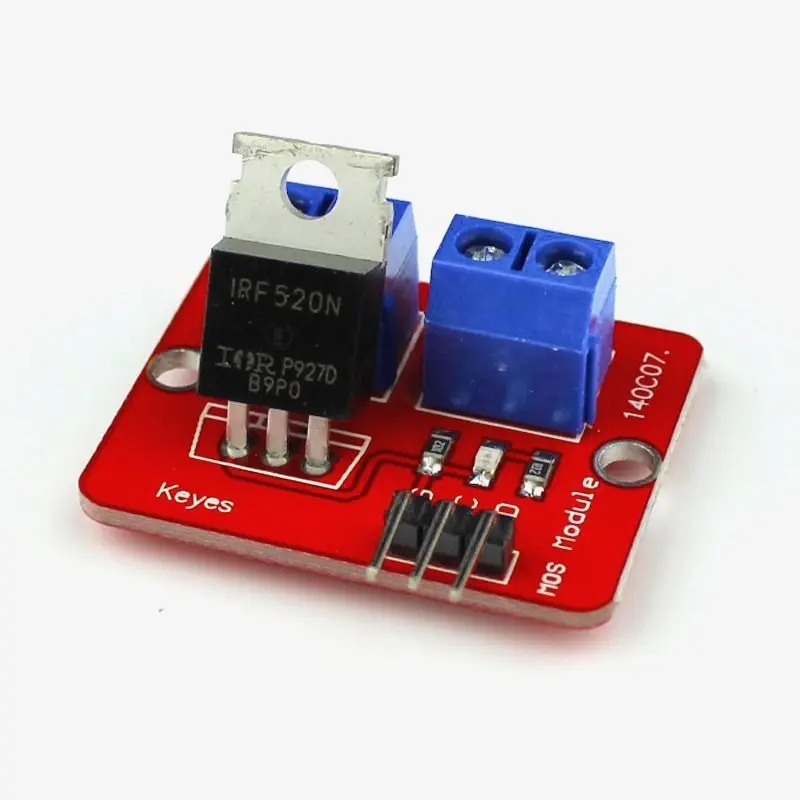
IRF520 MOSFET Driver Module Red
This module's backbone is the IRF520 MOSFET transistor (HCMODU0083). The module's purpose is to switch substantial DC loads that are powered by a single digital microcontroller pin. It can be used to drive most high-current DC loads, but its main usage is to provide a cheap way to drive a DC motor for robotics applications.
Package Includes:
- 1 x IRF520 MOSFET Driver Module Red
Features:
-
Platform: Arduino, MCU, ARM, Raspberry Pi.
-
Using the original IRF520 Power MOS, you can adjust the output PWM.
-
Drive up to 24V allows the load, such as LED lights, DC motors, miniature pumps, and solenoid valves.
-
PWM dimming LED can be used to achieve step-less dimming and variable-speed motor control.
Note: Above the 1A load, you need to install the heat sink.
Principle of Work:
This module uses the PWM (Pulse Width Modulation) method to operate DC motors. These modules change the input voltage from constant to variable. The voltage applied across a DC motor can also be changed to alter its speed. PWMs typically operate at a fixed frequency and can regulate the engine speed by adjusting how long the pulse remains HIGH (Duty Cycle). Engine speed control modules are incredibly flexible and simple to operate.
Pinout of the Module:
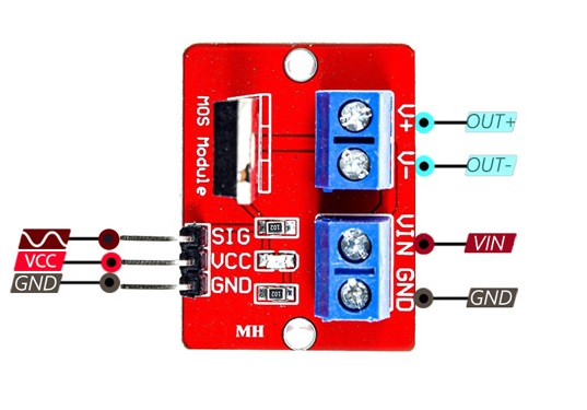
- VCC: Module power supply – 5V
- GND: Ground
- SIG: PWM input signal
- Vin: Input voltage 5-24 V
- OUT: Module output for connecting to a motor
Applications:
- LED Dimming
- Motor speed control
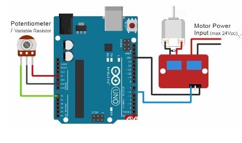
Circuit:
To get this circuit to work you will need a PWM source, you could use an Arduino with Pot and program one of the board PWM pins to act like a PWM source. with this set up you will be able to control a motor or LED strip with a voltage between 5 and 24v.
Library:
This Module doesn't need a library to work.
Code:
void setup() {
pinMode(6,1);
}

void loop() {
int a = analogRead(A0);
analogWrite(6,a/4);
delay(50);
}
Technical Details:
- Voltage control 3.3V to 5V
- maximum output voltage ± 24V
- Output current <1A
- with heat sink up to 5A are possible
- Dimensions 35mm x 25mm
- Weight 7.5g
Resources:
Comparisons:
The IRF520 module works exactly the same as the LR7843 but the only difference is that IRF520 doesn't include an optocoupler which means there is no real isolation between the input and the output which might damage the MCU in some cases that is an advantage to the LR7843 and also the IRF520 has lower max voltage.
Features:
-
Platform: Arduino, MCU, ARM, Raspberry Pi.
-
Using the original IRF520 Power MOS, you can adjust the output PWM.
-
Drive up to 24V allows the load, such as LED lights, DC motors, miniature pumps, and solenoid valves.
-
PWM dimming LED can be used to achieve step-less dimming and variable-speed motor control.
Note: Above the 1A load, you need to install the heat sink.
Principle of Work:
This module uses the PWM (Pulse Width Modulation) method to operate DC motors. These modules change the input voltage from constant to variable. The voltage applied across a DC motor can also be changed to alter its speed. PWMs typically operate at a fixed frequency and can regulate the engine speed by adjusting how long the pulse remains HIGH (Duty Cycle). Engine speed control modules are incredibly flexible and simple to operate.
Pinout of the Module:
- VCC: Module power supply – 5V
- GND: Ground
- SIG: PWM input signal
- Vin: Input voltage 5-24 V
- OUT: Module output for connecting to a motor
Applications:
- LED Dimming
- Motor speed control
Circuit:
To get this circuit to work you will need a PWM source, you could use an Arduino with Pot and program one of the board PWM pins to act like a PWM source. with this set up you will be able to control a motor or LED strip with a voltage between 5 and 24v.
Library:
This Module doesn't need a library to work.
Code:
void setup() {
pinMode(6,1);
}

void loop() {
int a = analogRead(A0);
analogWrite(6,a/4);
delay(50);
}
Technical Details:
- Voltage control 3.3V to 5V
- maximum output voltage ± 24V
- Output current <1A
- with heat sink up to 5A are possible
- Dimensions 35mm x 25mm
- Weight 7.5g
Resources:
Comparisons:
The IRF520 module works exactly the same as the LR7843 but the only difference is that IRF520 doesn't include an optocoupler which means there is no real isolation between the input and the output which might damage the MCU in some cases that is an advantage to the LR7843 and also the IRF520 has lower max voltage.