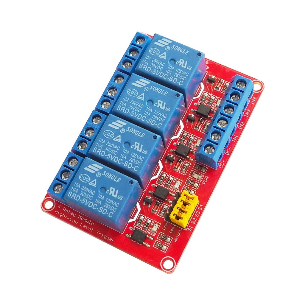
Relay Module Board 4 Channel 5V 10A with Optocoupler Active Low Triggered
The 4-Channel Relay Interface Board is a robust and efficient module designed for controlling high-current appliances and equipment. Operating at 5V, each channel requires only 15–20mA driver current, ensuring optimal performance with minimal power consumption. With relays rated at AC250V 10A or DC30V 10A, this board is ideal for switching a wide variety of devices.
Safety is built-in — optical isolators ensure that high voltage on the load side does not affect the control side. Thanks to its standard interface, the board can be easily connected and controlled directly via a microcontroller.
Package Includes:
- 1 x 4-Channel Relay Module (Low Trigger)
Features:
- Optocoupler Isolation: Reduces distortion and improves signal reliability.
- Dual Contact Design: Each relay provides Normally Closed (NC) and Normally Open (NO) contacts for flexible switching.
- High-Impedance Input: Ensures seamless interfacing with microcontrollers.
- Indicator LEDs: Power and channel status indicators for easy monitoring.
- Configurable Power: JD-VCC and VCC jumper for flexible power supply separation.
Principle of Work:
- Low Trigger Operation: Sending a LOW signal (0V or GND) to an input pin activates the corresponding relay.
- LED Indicators: Each channel has a status LED that lights when the relay is active.
- JD-VCC & VCC Jumper: Allows separating relay coil power from control circuit power for improved safety.
- Relay Outputs: Each relay provides NC, NO, and COM terminals for load control.
- Optical Isolation: Protects microcontrollers from high-voltage interference on the load side.
Pinout:

| Pin | Description |
|---|---|
| VCC | 5V power input |
| GND | Ground |
| INT1–INT4 | Trigger inputs for each relay |
| JD-VCC | Relay coil power |
| NC | Normally Closed contact |
| COM | Common terminal |
| NO | Normally Open contact |
Applications:
- Home automation (lights, fans, appliances)
- Industrial and PLC control
- Security systems (door locks, alarms)
- Battery backup switching
- Energy management systems
- Automotive electrical control
Circuit Example:
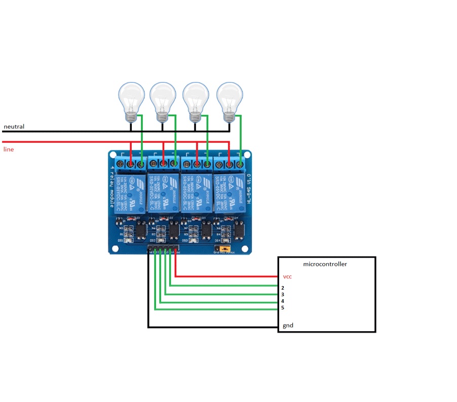
Arduino Code Example:
const int numRelays = 4;
const int relayPins[numRelays] = {2, 3, 4, 5};
const int delayTime = 1000;

void setup() {
  for (int i = 0; i < numRelays; i++) {
    pinMode(relayPins[i], OUTPUT);
    digitalWrite(relayPins[i], HIGH); // Relays OFF by default
  }
  Serial.begin(9600);
}

void loop() {
  for (int i = 0; i < numRelays; i++) {
    digitalWrite(relayPins[i], LOW); // Turn ON relay
    Serial.print("Relay "); Serial.print(i+1); Serial.println(" is ON");
    delay(delayTime);
  }
  for (int i = 0; i < numRelays; i++) {
    digitalWrite(relayPins[i], HIGH); // Turn OFF relay
    Serial.print("Relay "); Serial.print(i+1); Serial.println(" is OFF");
    delay(delayTime);
  }
}
Technical Details:
- Channels: 4
- Operating Voltage: 3.75V – 6V
- Trigger Current: 5mA – 15mA
- Active Current: ~70mA (1 relay), ~300mA (all relays)
- Relay Rating: 250VAC 10A / 30VDC 10A
- Isolation: Optical isolators onboard
Comparison: Mechanical vs SSR Relays
- Mechanical Relays: Faster response, cost-effective, shorter lifespan.
- Solid-State Relays (SSR): Noiseless, longer lifespan, compact, energy-efficient.
Features:
- Optocoupler Isolation: Reduces distortion and improves signal reliability.
- Dual Contact Design: Each relay provides Normally Closed (NC) and Normally Open (NO) contacts for flexible switching.
- High-Impedance Input: Ensures seamless interfacing with microcontrollers.
- Indicator LEDs: Power and channel status indicators for easy monitoring.
- Configurable Power: JD-VCC and VCC jumper for flexible power supply separation.
Principle of Work:
- Low Trigger Operation: Sending a LOW signal (0V or GND) to an input pin activates the corresponding relay.
- LED Indicators: Each channel has a status LED that lights when the relay is active.
- JD-VCC & VCC Jumper: Allows separating relay coil power from control circuit power for improved safety.
- Relay Outputs: Each relay provides NC, NO, and COM terminals for load control.
- Optical Isolation: Protects microcontrollers from high-voltage interference on the load side.
Pinout:
| Pin | Description |
|---|---|
| VCC | 5V power input |
| GND | Ground |
| INT1–INT4 | Trigger inputs for each relay |
| JD-VCC | Relay coil power |
| NC | Normally Closed contact |
| COM | Common terminal |
| NO | Normally Open contact |
Applications:
- Home automation (lights, fans, appliances)
- Industrial and PLC control
- Security systems (door locks, alarms)
- Battery backup switching
- Energy management systems
- Automotive electrical control
Circuit Example:
Arduino Code Example:
const int numRelays = 4;
const int relayPins[numRelays] = {2, 3, 4, 5};
const int delayTime = 1000;

void setup() {
  for (int i = 0; i < numRelays; i++) {
    pinMode(relayPins[i], OUTPUT);
    digitalWrite(relayPins[i], HIGH); // Relays OFF by default
  }
  Serial.begin(9600);
}

void loop() {
  for (int i = 0; i < numRelays; i++) {
    digitalWrite(relayPins[i], LOW); // Turn ON relay
    Serial.print("Relay "); Serial.print(i+1); Serial.println(" is ON");
    delay(delayTime);
  }
  for (int i = 0; i < numRelays; i++) {
    digitalWrite(relayPins[i], HIGH); // Turn OFF relay
    Serial.print("Relay "); Serial.print(i+1); Serial.println(" is OFF");
    delay(delayTime);
  }
}
Technical Details:
- Channels: 4
- Operating Voltage: 3.75V – 6V
- Trigger Current: 5mA – 15mA
- Active Current: ~70mA (1 relay), ~300mA (all relays)
- Relay Rating: 250VAC 10A / 30VDC 10A
- Isolation: Optical isolators onboard
Comparison: Mechanical vs SSR Relays
- Mechanical Relays: Faster response, cost-effective, shorter lifespan.
- Solid-State Relays (SSR): Noiseless, longer lifespan, compact, energy-efficient.