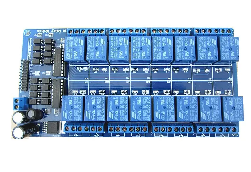
Relay Module Board 16 Channel 5V 10A With Optocoupler and LM2576 Voltage Power Converter
This is a 5V 16 Channel Active Low Relay Module with Light Coupling LM2576 Power Supply that can control various appliances and other high-current equipment. Microcontrollers can directly control it. Each individual relay requires 15-20mA of driver current. The board includes an LED that indicates the status of the relay output and a standard interface that can be controlled directly by many popular microcontrollers such as Arduino.
Package Includes:
- 1 x 5V 16 Channel Relay Module Low Trigger with Optocouplers and LM2576buck converter
Features:
- 5V relay with AC contact capacity of 10A 250V and optocoupler protection.
- The onboard power supply module does not need an external power supply. I / O port driver is active and low.
- The module can be used as a microcontroller development board module and also as appliance control, PLC extended output.
- It is using the industry’s top-quality isolation optocouplers, strong anti-jamming ability, and stable performance.
- The 1-16 road can be any full on/off or any road.
- All interfaces can be directly connected through the terminal leads, very convenient.
Principle of Work:
An iron core is surrounded by a control coil. As shown, the power source is given to the electromagnet through a control switch and through contacts to the load. When current starts flowing through the control coil, the electromagnet starts energizing and thus intensifies the magnetic field. Thus the upper contact arm starts to be attracted to the lower fixed arm and thus closes the contacts causing a short circuit for the power to the load. On the other hand, if the relay was already de-energized when the contacts were closed, then the contact move oppositely and make an open circuit.
As soon as the coil current is off, the movable armature will be returned by a force back to its initial position. This force will be almost equal to half the strength of the magnetic force. This force is mainly provided by two factors. They are spring and also gravity. Relays are mainly made for two basic operations. One is low voltage application and the other is high voltage. For low-voltage applications. and low-level triggered functionality will allow the current to go through the power line when the control signal is GND or close. optocoupler on the other hand makes real photo isolation between the relay and the MCU which is very good to minimize the distortion from the other side
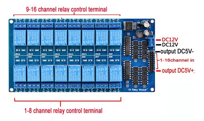
Pinout of the Module:

-
VCC DC +: Connected to 12v
-
DC -: Connected to GND
- NC: you connect your application here if you want it to be working all the time and stop when you attach input to GND
- COM: common always connected
- NO: you connect your application here if you want it to be Stopped all the time and starts working when you attach input to GND
Applications:
- Relay Drive from External Contacts.
- LED Series and Parallel Connections.
- Electronic Circuit Drive by Means of a Relay.
- Home automation
- Battery backup
- High current load switching
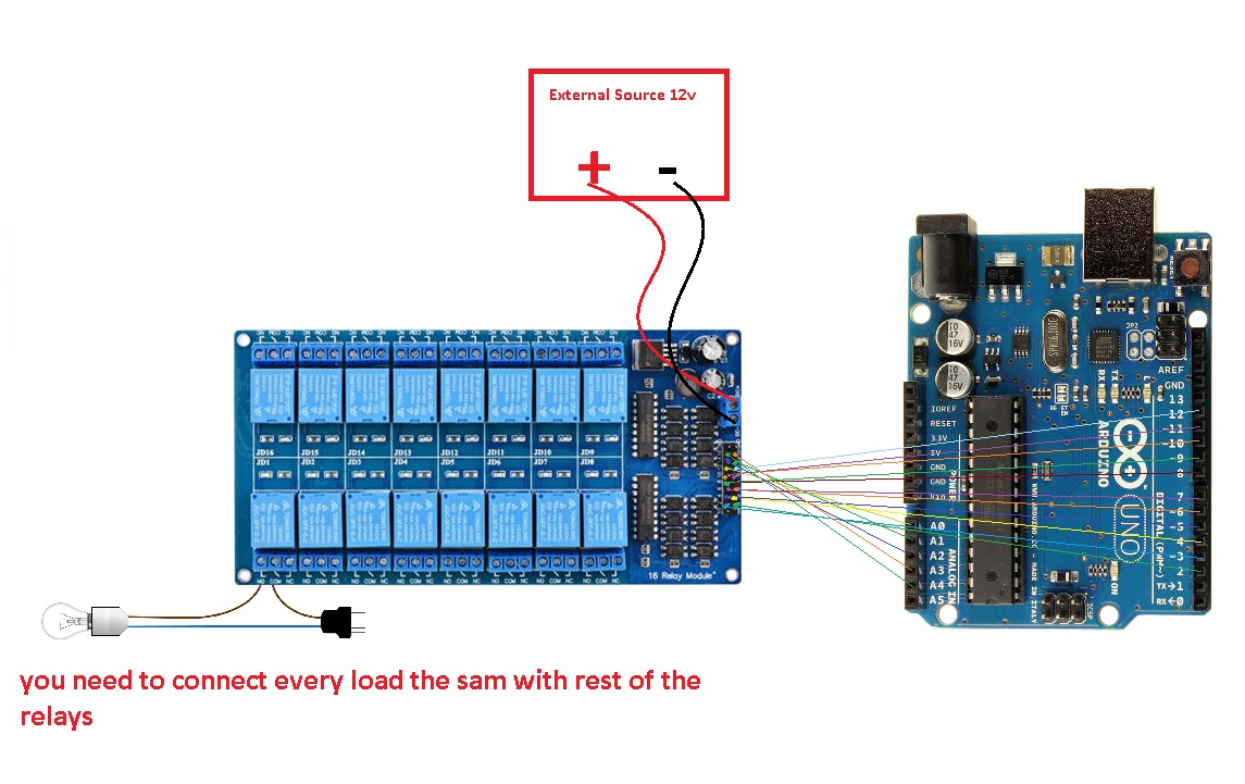
Circuit:
in this example, we will blink a 220v lamp for 1sec and shoot it down for 1sec you need to connect the 16 load the same
Library:
This Module doesn't need a library to work.
Code:
const int controlPin[16] = {2,3,4,5,6,7,8,9,10,11,12,A0,A1,A2,A3,A4}; // define pins
const int triggerType = LOW;// your relay type
int loopDelay = 1000;// delay in loop
int tmpStat =1;
void setup() {
 for(int i=0; i<16; i++)
 {
 pinMode(controlPin[i], OUTPUT);// set pin as output
 if(triggerType ==LOW){
 digitalWrite(controlPin[i], HIGH); // set initial state OFF for low trigger relay
 }else{
 digitalWrite(controlPin[i], LOW); // set initial state OFF for high trigger relay
 }
 }
 Serial.begin(9600);// initialize serial monitor with 9600 baud
}
void loop() {
 for(int i=0; i<16; i++)
 {
 channelControl(i,tmpStat,200);// turn each relay ON for 200ms
 }
 if(tmpStat)
 {
 tmpStat=0;
 }else{
 tmpStat=1;
 }
 Serial.println("===============");
 //channelControl(6,1, 2000); // turn relay 7 ON for 2 seconds
 //channelControl(6,0, 5000); // turn relay 7 OFF for 5 seconds
 //channelControl(9,1, 3000); // turn relay 10 OFF for ever
 delay(loopDelay);// wait for loopDelay ms
}
/*
 * funciton: channelControl
 * turns ON or OFF specific relay channel
 * @param relayChannel is integer value channel from 0 to 15
 * @param action is 1 for ON or 0 for OFF
 * @param t is time in melisecond
 */
void channelControl(int relayChannel, int action, int t)
{
 int state =LOW;
 String statTXT =" ON";
 if(triggerType == LOW)
 {
 if (action ==0)// if OFF requested
 {
 state = HIGH;
 statTXT = " OFF";
 }
 digitalWrite(controlPin[relayChannel], state);
 if(t >0 )
 {
 delay(t);
 }
 Serial.print ("Channel: ");
 Serial.print(relayChannel);
 Serial.print(statTXT);
 Serial.print(" - ");
 Serial.println(t);
 }else{
 if (action ==1)// if ON requested
 {
 state = HIGH;
 }else{
 statTXT = " OFF";
 }
 digitalWrite(controlPin[relayChannel], state);
 if(t >0 )
 {
 delay(t);
 }
 Serial.print ("Channel: ");
 Serial.print(relayChannel);
 Serial.print(statTXT);
 Serial.print(" - ");
 Serial.println(t);
 }
}
Technical Details:
| Channel |
16 |
| Operating Voltage (VDC) |
5 |
| Trigger Voltage (VDC) |
5 |
| Trigger Current (mA) |
20 |
| Switching Voltage (VAC) |
250@10A |
| Switching Voltage (VDC) |
30@10A |
| Length (mm) |
180 |
| Width (mm) |
90 |
| Height (mm) |
20 |
| Weight (gm) |
220 |
| Weight |
0.27 kg |
| Dimensions |
16 × 8 × 3 cm |
Comparisons:
The board has 16 relays every relay has an LED so you can identify the latched one, the board has a buck converter on it that gives you the ability to power the board from 24v to 5 volts its better to use 12v, you don't need a specific external power source with a specific voltage, using an Active Low Triggered Relay Module comes with a price that you need to use a current to keep the application off on the other side of the relay or you can use this board with the application where needed to be on all the time and turn it off less often or simple you can connect the application on the NO side instead of the normal connecting. the optocoupler on the other hand is very useful this device lowers the distortion from the power lines and makes the circuit more isolated and better than the boards where no such a device is included so you always need to connect the GND of the MCU GND of the circuit which is not very good idea sometimes if we want to compare it to this item (Relay Module Board 8 channel 5V 2Rows with Optocoupler) you can say both are very similar both has optocouplers led for every relay the 2row board is a very compact in size but the 16relay ones have more relays and ha a buck converter on board which makes wiring and connecting easier.
This kind of relay board has so many advantages like being able to withstand large inrush currents and high mechanical structure reliability, not being susceptible to the external electromagnetic environment, and being able to carry high voltage, and high current load but still, it has multiple disadvantages to the SSR Boards that they are slower than SSRs at 5 to 15ms and it has a larger package size, are not suitable for small projects and electromechanical relays tend to have a shorter life than other types of relays due to mechanical wear if you interested in SSRs you can get it from here
Features:
- 5V relay with AC contact capacity of 10A 250V and optocoupler protection.
- The onboard power supply module does not need an external power supply. I / O port driver is active and low.
- The module can be used as a microcontroller development board module and also as appliance control, PLC extended output.
- It is using the industry’s top-quality isolation optocouplers, strong anti-jamming ability, and stable performance.
- The 1-16 road can be any full on/off or any road.
- All interfaces can be directly connected through the terminal leads, very convenient.
Principle of Work:
An iron core is surrounded by a control coil. As shown, the power source is given to the electromagnet through a control switch and through contacts to the load. When current starts flowing through the control coil, the electromagnet starts energizing and thus intensifies the magnetic field. Thus the upper contact arm starts to be attracted to the lower fixed arm and thus closes the contacts causing a short circuit for the power to the load. On the other hand, if the relay was already de-energized when the contacts were closed, then the contact move oppositely and make an open circuit.
As soon as the coil current is off, the movable armature will be returned by a force back to its initial position. This force will be almost equal to half the strength of the magnetic force. This force is mainly provided by two factors. They are spring and also gravity. Relays are mainly made for two basic operations. One is low voltage application and the other is high voltage. For low-voltage applications. and low-level triggered functionality will allow the current to go through the power line when the control signal is GND or close. optocoupler on the other hand makes real photo isolation between the relay and the MCU which is very good to minimize the distortion from the other side
Pinout of the Module:
-
VCC DC +: Connected to 12v
-
DC -: Connected to GND
- NC: you connect your application here if you want it to be working all the time and stop when you attach input to GND
- COM: common always connected
- NO: you connect your application here if you want it to be Stopped all the time and starts working when you attach input to GND
Applications:
- Relay Drive from External Contacts.
- LED Series and Parallel Connections.
- Electronic Circuit Drive by Means of a Relay.
- Home automation
- Battery backup
- High current load switching
Circuit:
in this example, we will blink a 220v lamp for 1sec and shoot it down for 1sec you need to connect the 16 load the same
Library:
This Module doesn't need a library to work.
Code:
const int controlPin[16] = {2,3,4,5,6,7,8,9,10,11,12,A0,A1,A2,A3,A4}; // define pins
const int triggerType = LOW;// your relay type
int loopDelay = 1000;// delay in loop
int tmpStat =1;
void setup() {
 for(int i=0; i<16; i++)
 {
 pinMode(controlPin[i], OUTPUT);// set pin as output
 if(triggerType ==LOW){
 digitalWrite(controlPin[i], HIGH); // set initial state OFF for low trigger relay
 }else{
 digitalWrite(controlPin[i], LOW); // set initial state OFF for high trigger relay
 }
 }
 Serial.begin(9600);// initialize serial monitor with 9600 baud
}
void loop() {
 for(int i=0; i<16; i++)
 {
 channelControl(i,tmpStat,200);// turn each relay ON for 200ms
 }
 if(tmpStat)
 {
 tmpStat=0;
 }else{
 tmpStat=1;
 }
 Serial.println("===============");
 //channelControl(6,1, 2000); // turn relay 7 ON for 2 seconds
 //channelControl(6,0, 5000); // turn relay 7 OFF for 5 seconds
 //channelControl(9,1, 3000); // turn relay 10 OFF for ever
 delay(loopDelay);// wait for loopDelay ms
}
/*
 * funciton: channelControl
 * turns ON or OFF specific relay channel
 * @param relayChannel is integer value channel from 0 to 15
 * @param action is 1 for ON or 0 for OFF
 * @param t is time in melisecond
 */
void channelControl(int relayChannel, int action, int t)
{
 int state =LOW;
 String statTXT =" ON";
 if(triggerType == LOW)
 {
 if (action ==0)// if OFF requested
 {
 state = HIGH;
 statTXT = " OFF";
 }
 digitalWrite(controlPin[relayChannel], state);
 if(t >0 )
 {
 delay(t);
 }
 Serial.print ("Channel: ");
 Serial.print(relayChannel);
 Serial.print(statTXT);
 Serial.print(" - ");
 Serial.println(t);
 }else{
 if (action ==1)// if ON requested
 {
 state = HIGH;
 }else{
 statTXT = " OFF";
 }
 digitalWrite(controlPin[relayChannel], state);
 if(t >0 )
 {
 delay(t);
 }
 Serial.print ("Channel: ");
 Serial.print(relayChannel);
 Serial.print(statTXT);
 Serial.print(" - ");
 Serial.println(t);
 }
}
Technical Details:
| Channel |
16 |
| Operating Voltage (VDC) |
5 |
| Trigger Voltage (VDC) |
5 |
| Trigger Current (mA) |
20 |
| Switching Voltage (VAC) |
250@10A |
| Switching Voltage (VDC) |
30@10A |
| Length (mm) |
180 |
| Width (mm) |
90 |
| Height (mm) |
20 |
| Weight (gm) |
220 |
| Weight |
0.27 kg |
| Dimensions |
16 × 8 × 3 cm |
Comparisons:
The board has 16 relays every relay has an LED so you can identify the latched one, the board has a buck converter on it that gives you the ability to power the board from 24v to 5 volts its better to use 12v, you don't need a specific external power source with a specific voltage, using an Active Low Triggered Relay Module comes with a price that you need to use a current to keep the application off on the other side of the relay or you can use this board with the application where needed to be on all the time and turn it off less often or simple you can connect the application on the NO side instead of the normal connecting. the optocoupler on the other hand is very useful this device lowers the distortion from the power lines and makes the circuit more isolated and better than the boards where no such a device is included so you always need to connect the GND of the MCU GND of the circuit which is not very good idea sometimes if we want to compare it to this item (Relay Module Board 8 channel 5V 2Rows with Optocoupler) you can say both are very similar both has optocouplers led for every relay the 2row board is a very compact in size but the 16relay ones have more relays and ha a buck converter on board which makes wiring and connecting easier.
This kind of relay board has so many advantages like being able to withstand large inrush currents and high mechanical structure reliability, not being susceptible to the external electromagnetic environment, and being able to carry high voltage, and high current load but still, it has multiple disadvantages to the SSR Boards that they are slower than SSRs at 5 to 15ms and it has a larger package size, are not suitable for small projects and electromechanical relays tend to have a shorter life than other types of relays due to mechanical wear if you interested in SSRs you can get it from here