Features:
- MFRC522 Chipset for reliable 13.56MHz RFID communication.
- Supports ISO 14443A / MIFARE protocol.
- Fast and stable contactless data transmission.
- Compact and lightweight module design.
- SPI interface for easy communication with microcontrollers.
- Low power consumption with sleep mode support.
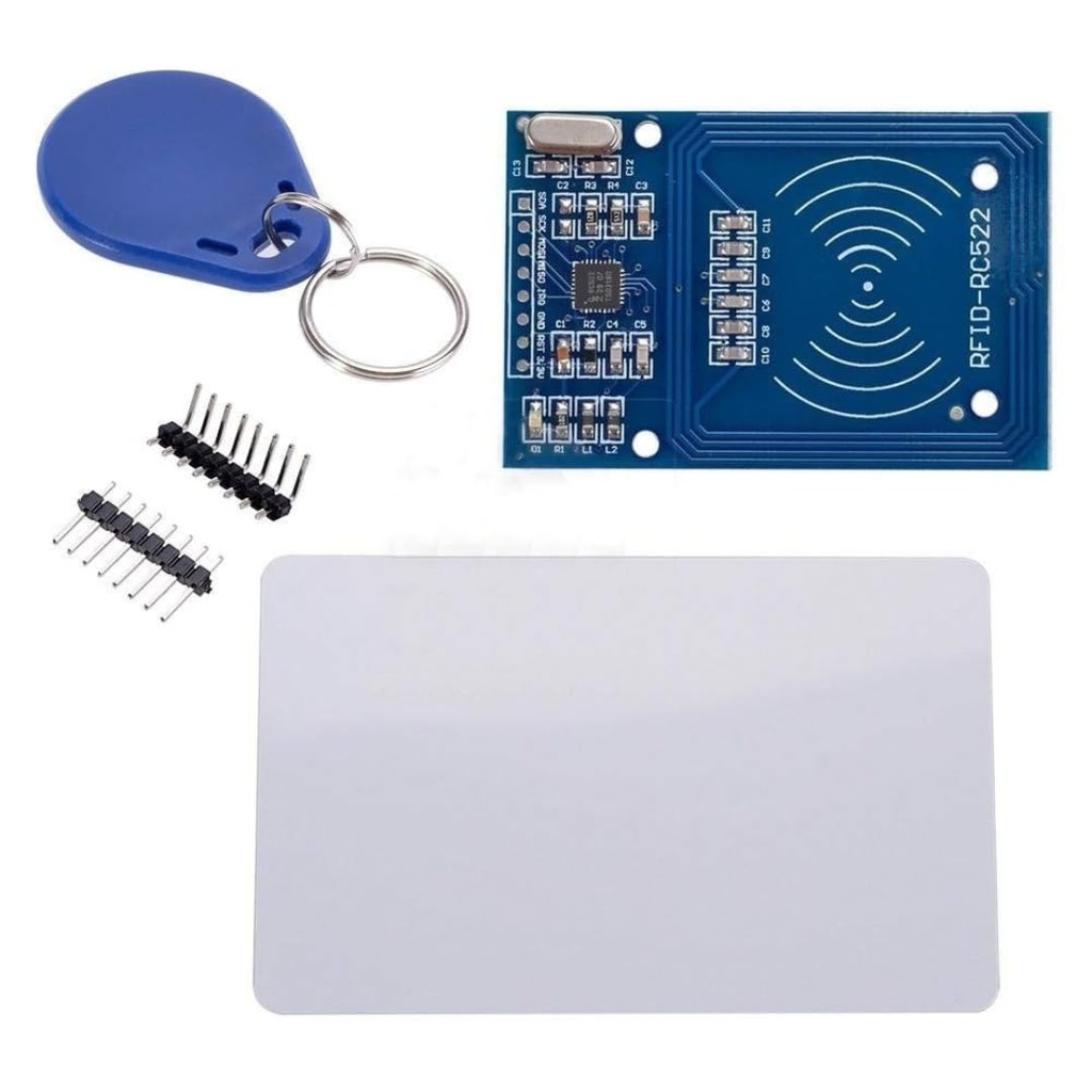
- Includes RFID card and keychain tag for immediate use.
- High security with unique UID identification.
- Suitable for Arduino, ESP8266, ESP32, and other platforms.
Principle of Work:
The RC522 RFID module works by generating an electromagnetic field at 13.56MHz, which powers passive RFID tags and enables data exchange.
- RF Field Generation: The module creates a radio-frequency field to activate RFID tags.
- Tag Communication: Tags respond with their unique UID via modulation.
- Data Processing: The MFRC522 chip decodes the received data.
- Microcontroller Interface: Data is transferred via SPI to a controller for processing.
Applications:
- Access control systems.
- Attendance tracking systems.
- Smart home security projects.
- Contactless payment prototypes.
- Inventory and asset tracking.
Pinout of the Module:
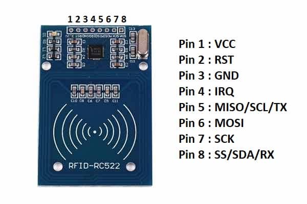
| Pin | Function | Description |
|---|---|---|
| SDA (SS) | SPI Chip Select | Selects the RFID module |
| SCK | SPI Clock | Clock signal for SPI communication |
| MOSI | SPI Data Input | Master Out Slave In |
| MISO | SPI Data Output | Master In Slave Out |
| IRQ | Interrupt | Interrupt signal (optional) |
| GND | Ground | Common ground |
| RST | Reset | Resets the module |
| 3.3V | Power | 3.3V supply (IMPORTANT: not 5V) |
Circuit: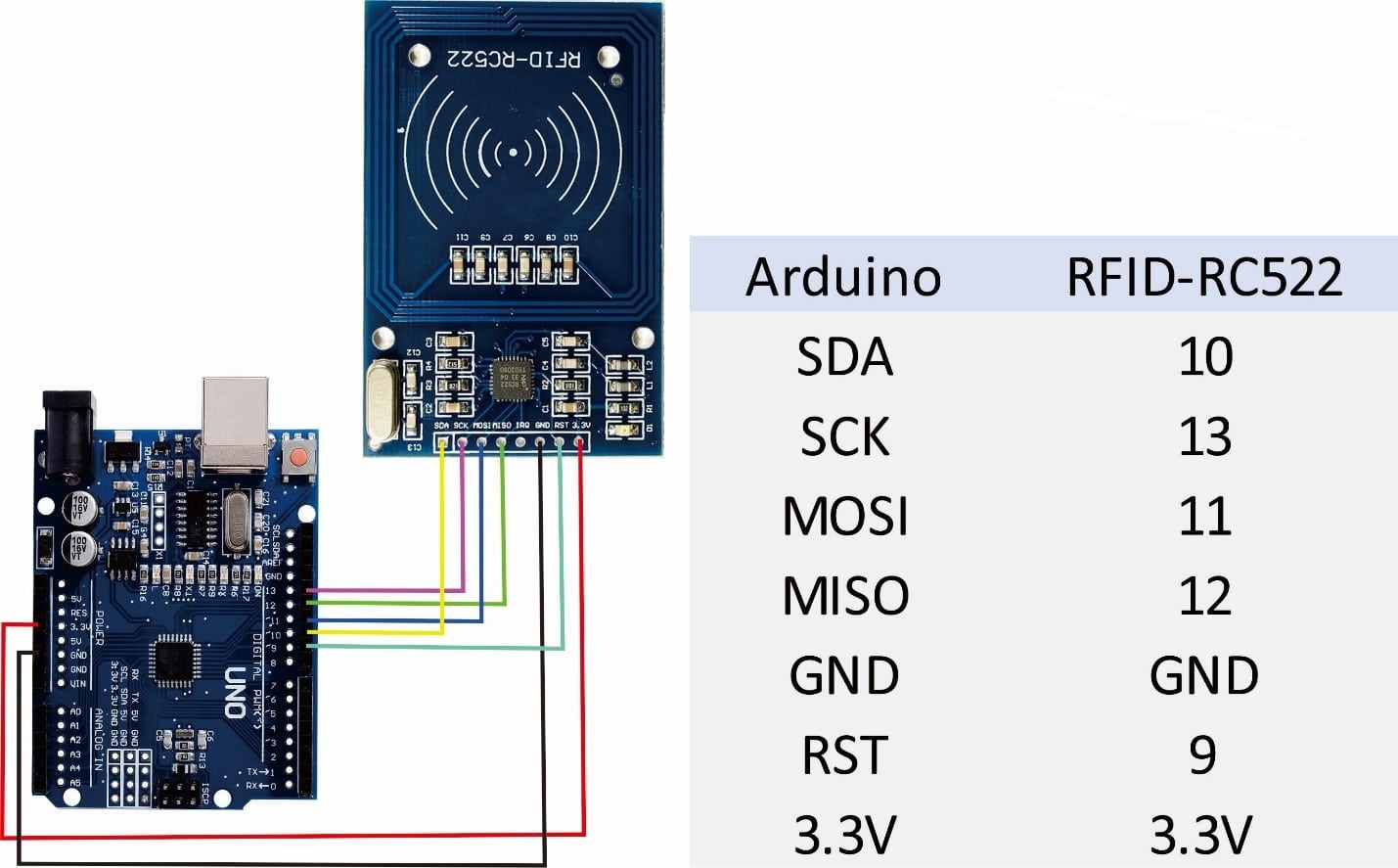
- Connect the module to your microcontroller (Arduino/ESP) using the SPI interface.
- Ensure power supply is 3.3V only (do NOT use 5V).
- Install the MFRC522 library in Arduino IDE.
- Open example: ReadUID from the library.
- Upload the code to your board.
- Open Serial Monitor.
- Place RFID card/tag near the module to read UID.
Code:
Basic Arduino Example (Read RFID UID):
#include <SPI.h>
#include <MFRC522.h>

#define SS_PIN 10
#define RST_PIN 9

MFRC522 rfid(SS_PIN, RST_PIN);

void setup() {
  Serial.begin(9600);
  SPI.begin();
  rfid.PCD_Init();
  Serial.println("Scan RFID card...");
}

void loop() {
  if (!rfid.PICC_IsNewCardPresent()) return;
  if (!rfid.PICC_ReadCardSerial()) return;

  Serial.print("UID: ");
  for (byte i = 0; i < rfid.uid.size; i++) {
    Serial.print(rfid.uid.uidByte[i], HEX);
    Serial.print(" ");
  }
  Serial.println();
}
Technical Details:
- Operating Voltage: 3.3V
- Operating Current: 13–26mA
- Idle Current: 10–13mA
- Sleep Current: <80µA
- Peak Current: <50mA
- Operating Frequency: 13.56MHz
- Supported Cards: MIFARE S50, S70, Ultralight, Pro
- Interface: SPI
- Data Rate: Up to 10Mbit/s
Features:
- MFRC522 Chipset for reliable 13.56MHz RFID communication.
- Supports ISO 14443A / MIFARE protocol.
- Fast and stable contactless data transmission.
- Compact and lightweight module design.
- SPI interface for easy communication with microcontrollers.
- Low power consumption with sleep mode support.
- Includes RFID card and keychain tag for immediate use.
- High security with unique UID identification.
- Suitable for Arduino, ESP8266, ESP32, and other platforms.
Principle of Work:
The RC522 RFID module works by generating an electromagnetic field at 13.56MHz, which powers passive RFID tags and enables data exchange.
- RF Field Generation: The module creates a radio-frequency field to activate RFID tags.
- Tag Communication: Tags respond with their unique UID via modulation.
- Data Processing: The MFRC522 chip decodes the received data.
- Microcontroller Interface: Data is transferred via SPI to a controller for processing.
Applications:
- Access control systems.
- Attendance tracking systems.
- Smart home security projects.
- Contactless payment prototypes.
- Inventory and asset tracking.
Pinout of the Module:
| Pin | Function | Description |
|---|---|---|
| SDA (SS) | SPI Chip Select | Selects the RFID module |
| SCK | SPI Clock | Clock signal for SPI communication |
| MOSI | SPI Data Input | Master Out Slave In |
| MISO | SPI Data Output | Master In Slave Out |
| IRQ | Interrupt | Interrupt signal (optional) |
| GND | Ground | Common ground |
| RST | Reset | Resets the module |
| 3.3V | Power | 3.3V supply (IMPORTANT: not 5V) |
Circuit:
- Connect the module to your microcontroller (Arduino/ESP) using the SPI interface.
- Ensure power supply is 3.3V only (do NOT use 5V).
- Install the MFRC522 library in Arduino IDE.
- Open example: ReadUID from the library.
- Upload the code to your board.
- Open Serial Monitor.
- Place RFID card/tag near the module to read UID.
Code:
Basic Arduino Example (Read RFID UID):
#include <SPI.h>
#include <MFRC522.h>

#define SS_PIN 10
#define RST_PIN 9

MFRC522 rfid(SS_PIN, RST_PIN);

void setup() {
  Serial.begin(9600);
  SPI.begin();
  rfid.PCD_Init();
  Serial.println("Scan RFID card...");
}

void loop() {
  if (!rfid.PICC_IsNewCardPresent()) return;
  if (!rfid.PICC_ReadCardSerial()) return;

  Serial.print("UID: ");
  for (byte i = 0; i < rfid.uid.size; i++) {
    Serial.print(rfid.uid.uidByte[i], HEX);
    Serial.print(" ");
  }
  Serial.println();
}
Technical Details:
- Operating Voltage: 3.3V
- Operating Current: 13–26mA
- Idle Current: 10–13mA
- Sleep Current: <80µA
- Peak Current: <50mA
- Operating Frequency: 13.56MHz
- Supported Cards: MIFARE S50, S70, Ultralight, Pro
- Interface: SPI
- Data Rate: Up to 10Mbit/s