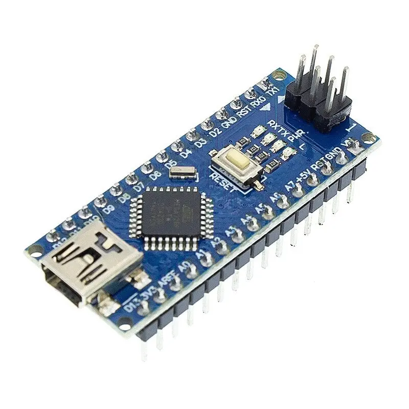
Arduino Nano V3 ATmega328 CH340 Soldered (Compatible)
The Arduino Nano v3 CH340 is a compact and cost-effective microcontroller board built around the powerful ATmega328P microcontroller and CH340 USB-to-serial chip. It is fully compatible with the Arduino IDE and ideal for breadboard use and space-constrained projects.
Package Includes:
- 1 x Arduino Nano v3 ATmega328P - CH340 (Soldered)
Features:
- Microcontroller: ATmega328P (32KB Flash, 2KB SRAM, 1KB EEPROM)
- USB-to-Serial Chip: CH340
- Digital I/O Pins: 14 (6 with PWM support)
- Analog Inputs: 8
- Clock Speed: 16 MHz Quartz Crystal
- Compatibility: Fully compatible with Arduino IDE
- Breadboard-Friendly: Compact size, fits standard breadboards
- Power Consumption: Energy-efficient design
- Onboard LEDs: Built-in status/debug LED on Pin 13
- Open-Source: Hardware design is open-source
- USB Programming: Program and power via USB
- Expandable: Supports various shields and modules
Principle of Work:
This board operates via the ATmega328P microcontroller, executing uploaded code and managing I/O tasks. The CH340 chip enables communication between the board and a computer through USB, allowing you to upload sketches and interact via the Serial Monitor.
Workflow:
- Install CH340 USB driver if needed: Download here
- Connect board via USB
- Select board type: "Arduino Nano" in Arduino IDE
- Select processor: "ATmega328P"
- Select correct COM port
- Upload code via Arduino IDE
Pinout of the Board:
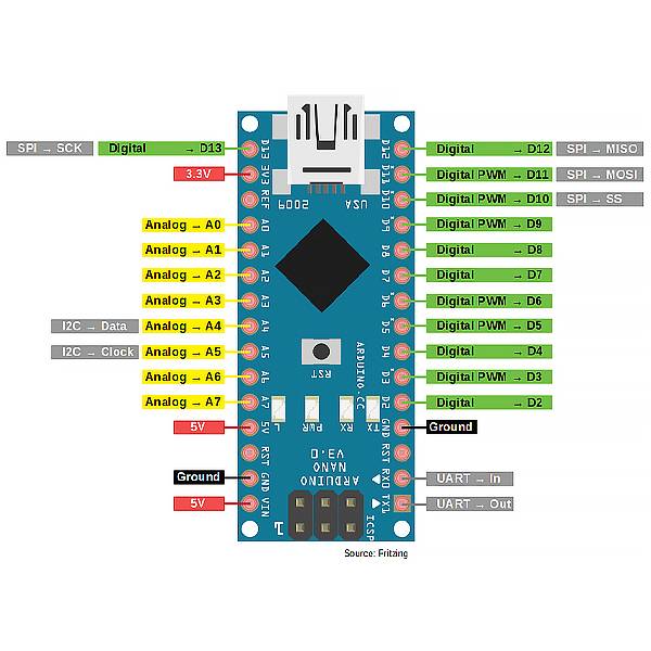
| Pin | Name | Function |
|---|---|---|
| 1 | D13 | Digital output (SPI clock) |
| 2 | D12 | Digital output (SPI MISO) |
| 3 | D11 | Digital output (SPI MOSI) |
| 4 | D10 | Digital output (SPI chip select) |
| 5 | D9 | Digital output (PWM) |
| 6 | D8 | Digital output (PWM) |
| 7 | D7 | Digital output |
| 8 | D6 | Digital output (PWM) |
| 9 | D5 | Digital output (PWM) |
| 10 | D4 | Digital output |
| 11 | D3 | Digital output (PWM) |
| 12 | D2 | Digital output |
| 13 | D1 | TX (UART) |
| 14 | D0 | RX (UART) |
| 15 | AREF | Analog reference voltage input |
| 16 | A0 | Analog input |
| 17 | A1 | Analog input |
| 18 | A2 | Analog input |
| 19 | A3 | Analog input |
| 20 | A4 | Analog/I2C SDA |
| 21 | A5 | Analog/I2C SCL |
| 22 | RESET | Reset |
| 23 | 5V | Power output |
| 24 | GND | Ground |
| 25 | Vin | Power input (7-12V) |
| 26 | NC | Not connected |
Applications:
- DIY electronics and home automation
- Robotics (e.g., line-followers, RC vehicles)
- Sensor data collection and environmental monitoring
- Wearables (e.g., smartwatches, fitness trackers)
- IoT systems with internet connectivity
- Educational electronics and STEM teaching
- Data logging using SD cards or Serial Monitor
- Art installations and interactive displays
- Automotive diagnostics or small-scale controls
- Wireless communication projects using Bluetooth/Wi-Fi
Sample Code:
void setup() {
  pinMode(LED_BUILTIN, OUTPUT); // Set LED pin as output
  Serial.begin(9600); // Start serial communication
}

void loop() {
  if (Serial.available()) {
    char command = Serial.read();
    if (command == '1') {
      digitalWrite(LED_BUILTIN, HIGH);
      Serial.println("LED turned on");
    } else if (command == '0') {
      digitalWrite(LED_BUILTIN, LOW);
      Serial.println("LED turned off");
    }
  }
}
Technical Specifications:
- Microcontroller: ATmega328P
- Clock Speed: 16 MHz
- Operating Voltage: 5V
- Input Voltage (Recommended): 7–12V
- Input Voltage (Limits): 6–20V
- Digital I/O Pins: 14 (6 PWM)
- Analog Inputs: 8
- Flash Memory: 32 KB (2 KB used by bootloader)
- SRAM: 2 KB
- EEPROM: 1 KB
- DC Current per I/O Pin: 20 mA
- DC Current for 3.3V Pin: 50 mA
- USB to Serial: CH340G
Resources:
Comparison: Nano v3 vs Pro Mini
| Feature | Arduino Nano v3 | Arduino Pro Mini |
|---|---|---|
| Form Factor | USB onboard, breadboard-friendly | Smaller, no USB |
| Microcontroller | ATmega328P | |
| Voltage | 5V | 3.3V / 5V versions |
| USB Interface | CH340G onboard | External FTDI adapter needed |
| Ease of Use | Plug & Play with Arduino IDE | Requires adapter and more setup |
Features:
- Microcontroller: ATmega328P (32KB Flash, 2KB SRAM, 1KB EEPROM)
- USB-to-Serial Chip: CH340
- Digital I/O Pins: 14 (6 with PWM support)
- Analog Inputs: 8
- Clock Speed: 16 MHz Quartz Crystal
- Compatibility: Fully compatible with Arduino IDE
- Breadboard-Friendly: Compact size, fits standard breadboards
- Power Consumption: Energy-efficient design
- Onboard LEDs: Built-in status/debug LED on Pin 13
- Open-Source: Hardware design is open-source
- USB Programming: Program and power via USB
- Expandable: Supports various shields and modules
Principle of Work:
This board operates via the ATmega328P microcontroller, executing uploaded code and managing I/O tasks. The CH340 chip enables communication between the board and a computer through USB, allowing you to upload sketches and interact via the Serial Monitor.
Workflow:
- Install CH340 USB driver if needed: Download here
- Connect board via USB
- Select board type: "Arduino Nano" in Arduino IDE
- Select processor: "ATmega328P"
- Select correct COM port
- Upload code via Arduino IDE
Pinout of the Board:
| Pin | Name | Function |
|---|---|---|
| 1 | D13 | Digital output (SPI clock) |
| 2 | D12 | Digital output (SPI MISO) |
| 3 | D11 | Digital output (SPI MOSI) |
| 4 | D10 | Digital output (SPI chip select) |
| 5 | D9 | Digital output (PWM) |
| 6 | D8 | Digital output (PWM) |
| 7 | D7 | Digital output |
| 8 | D6 | Digital output (PWM) |
| 9 | D5 | Digital output (PWM) |
| 10 | D4 | Digital output |
| 11 | D3 | Digital output (PWM) |
| 12 | D2 | Digital output |
| 13 | D1 | TX (UART) |
| 14 | D0 | RX (UART) |
| 15 | AREF | Analog reference voltage input |
| 16 | A0 | Analog input |
| 17 | A1 | Analog input |
| 18 | A2 | Analog input |
| 19 | A3 | Analog input |
| 20 | A4 | Analog/I2C SDA |
| 21 | A5 | Analog/I2C SCL |
| 22 | RESET | Reset |
| 23 | 5V | Power output |
| 24 | GND | Ground |
| 25 | Vin | Power input (7-12V) |
| 26 | NC | Not connected |
Applications:
- DIY electronics and home automation
- Robotics (e.g., line-followers, RC vehicles)
- Sensor data collection and environmental monitoring
- Wearables (e.g., smartwatches, fitness trackers)
- IoT systems with internet connectivity
- Educational electronics and STEM teaching
- Data logging using SD cards or Serial Monitor
- Art installations and interactive displays
- Automotive diagnostics or small-scale controls
- Wireless communication projects using Bluetooth/Wi-Fi
Sample Code:
void setup() {
  pinMode(LED_BUILTIN, OUTPUT); // Set LED pin as output
  Serial.begin(9600); // Start serial communication
}

void loop() {
  if (Serial.available()) {
    char command = Serial.read();
    if (command == '1') {
      digitalWrite(LED_BUILTIN, HIGH);
      Serial.println("LED turned on");
    } else if (command == '0') {
      digitalWrite(LED_BUILTIN, LOW);
      Serial.println("LED turned off");
    }
  }
}
Technical Specifications:
- Microcontroller: ATmega328P
- Clock Speed: 16 MHz
- Operating Voltage: 5V
- Input Voltage (Recommended): 7–12V
- Input Voltage (Limits): 6–20V
- Digital I/O Pins: 14 (6 PWM)
- Analog Inputs: 8
- Flash Memory: 32 KB (2 KB used by bootloader)
- SRAM: 2 KB
- EEPROM: 1 KB
- DC Current per I/O Pin: 20 mA
- DC Current for 3.3V Pin: 50 mA
- USB to Serial: CH340G
Resources:
Comparison: Nano v3 vs Pro Mini
| Feature | Arduino Nano v3 | Arduino Pro Mini |
|---|---|---|
| Form Factor | USB onboard, breadboard-friendly | Smaller, no USB |
| Microcontroller | ATmega328P | |
| Voltage | 5V | 3.3V / 5V versions |
| USB Interface | CH340G onboard | External FTDI adapter needed |
| Ease of Use | Plug & Play with Arduino IDE | Requires adapter and more setup |