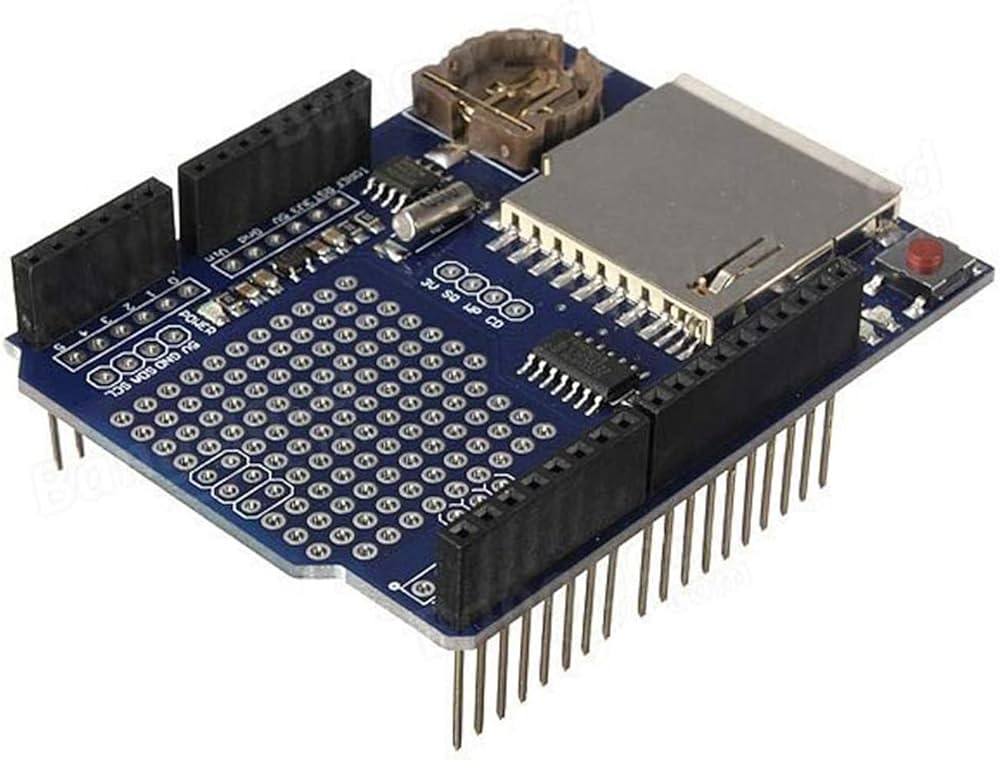
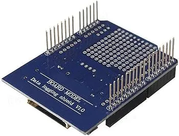
Features:
- SD card slot for storing large amounts of data
- Real-time clock module for accurate time-stamping of logged data
- Six analog input pins and four digital input/output pins for connecting to external sensors and devices
- Dedicated pin for connecting to a DS18B20 temperature sensor
- Compatible with both 3.3V and 5V Arduino boards
- Can be programmed using the Arduino IDE
- LED indicator for visual feedback on the shield's status
- Onboard reset button for easy operation
- Compact and easy to mount on top of an Arduino board
- Versatile and customizable for a wide range of data logging applications.
Principle of Work:
When the XD-204 shield is mounted on top of an Arduino board and powered on, it begins to log data from any sensors or devices that are connected to its input/output pins. The shield communicates with the Arduino board using the Serial Peripheral Interface (SPI) protocol, which allows it to read data from connected sensors and write the data to an SD card. The shield features a real-time clock module, which keeps track of the current time and date. This allows it to accurately time-stamp each data point as it is being logged. The clock module is powered by a backup battery, so even if the shield loses power, it will continue to keep track of time. To begin logging data, the user must first format an SD card to the FAT32 file system and insert it into the shield's SD card slot. They can then write a program in the Arduino IDE that reads data from sensors and writes it to the SD card. The program can be customized to meet the specific needs of the project or application. Once the data has been logged to the SD card, it can be transferred to a computer for analysis and visualization. This can be done by removing the SD card from the shield and inserting it into a card reader, or by connecting the Arduino board to a computer using a USB cable and transferring the data over a serial connection.
Pinout of the Transistor:
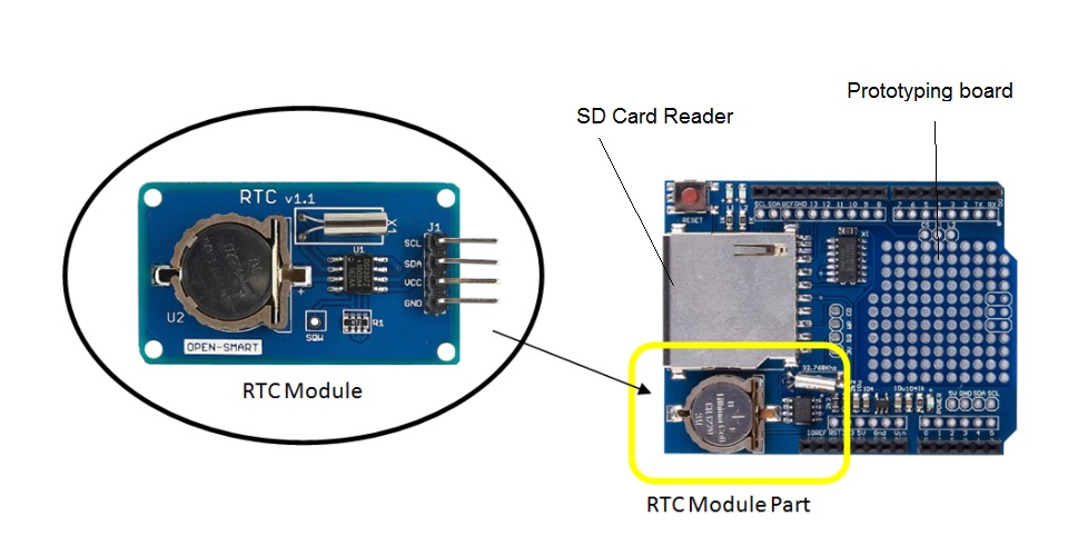
The combination of the RTC module, prototyping board, and SD card reader module makes the XD-204 shield a powerful and versatile tool for data-logging applications with Arduino. The RTC module provides accurate time-stamping of data, the prototyping board allows for custom circuits to be created, and the SD card reader module provides ample storage space for logged data.
- 5V: This pin provides +5V power to the shield and any connected sensors or devices.
- GND: This pin is the ground connection for the shield and any connected sensors or devices.
- CS: This is the chip select pin, which is used by the shield to communicate with the SD card.
- MOSI: This is the Master Out Slave In pin, which is used to send data from the shield to the SD card.
- MISO: This is the Master In Slave Out pin, which is used to receive data from the SD card to the shield.
- SCK: This is the Serial Clock pin, which is used to synchronize data transmission between the shield and the SD card.
- A0 - A5: These are the analog input pins, which can be used to read analog signals from external sensors or devices.
- D2 - D5: These are the digital input/output pins, which can be used to connect to external sensors or devices that require digital input or output.
- T: This is the pin used for connecting to a DS18B20 temperature sensor.
Applications:
- Environmental monitoring: The XD-204 shield can be used to log data from sensors that measure temperature, humidity, air quality, and other environmental parameters. This data can be used to monitor the health of indoor or outdoor environments over time.
- Agriculture and farming: The XD-204 shield can be used to log data from sensors that measure soil moisture, temperature, and other parameters relevant to plant growth. This data can be used to optimize irrigation schedules and identify patterns in plant growth over time.
- Industrial monitoring: The XD-204 shield can be used to log data from sensors that measure machine performance, vibration, temperature, and other parameters relevant to industrial processes. This data can be used to identify inefficiencies or potential problems in the manufacturing process.
- Home automation: The XD-204 shield can be used to log data from sensors that measure temperature, humidity, light levels, and other parameters relevant to home automation. This data can be used to control HVAC systems, lighting, and other home appliances to optimize energy use and comfort.
- Science education: The XD-204 shield can be used as a tool for teaching basic data logging and analysis concepts in science classes. Students can connect sensors to the shield, write programs to log data, and analyze the resulting data to draw conclusions and make predictions.
Circuit:
Just plug the shield in the Arduino UNO and you are good to go.
Library:
To use the RTC module in the next sample code, you need to install the RTClib library. Here's how to do it:
- Open the Arduino IDE and click on "Sketch" in the top menu bar.
- Hover over "Include Library" in the drop-down menu, and then click on "Manage Libraries..." in the sub-menu.
- In the Library Manager, search for "RTClib" in the search bar.
- Find the "RTClib" library in the search results and click on it.
- Click on the "Install" button to install the library.
- Wait for the installation process to complete, and then close the Library Manager.
the rest of the libraries are pre-installed in Arduino IDE
Code:
A sample code that demonstrates how to use the RTC and SD card reader on the Data Logger Arduino Shield XD-204, the code initializes the RTC module and the SD card reader on the XD-204 shield, creates a new file on the SD card for the log data, and then enters a loop where it reads the current date and time from the RTC module, reads the temperature from a sensor (not shown in this example), and then writes the date, time, and temperature to both the serial monitor and the log file on the SD card. The code waits for 5 seconds between readings to avoid flooding the log file with data:
#include "Wire.h"
#include "RTClib.h"
#include "SD.h"
RTC_DS1307 rtc; // create an RTC object
File logfile; // create a file object for the log file
void setup() {
 Serial.begin(9600);
 // initialize the RTC module
 if (!rtc.begin()) {
 Serial.println("RTC not found!");
 while (1);
 }
 // initialize the SD card
 if (!SD.begin(10)) {
 Serial.println("SD card initialization failed!");
 while (1);
 }
 // create a new file for the log data
 logfile = SD.open("datalog.txt", FILE_WRITE);
 // print a header to the log file
 logfile.print("Date/Time, Temperature");
}
void loop() {
 // get the current date and time from the RTC module
 DateTime now = rtc.now();
 // read the temperature from a sensor (not shown in this example)
 float temperature = 23.5;
 // write the date, time, and temperature to the serial monitor
 Serial.print(now.year(), DEC);
 Serial.print('/');
 Serial.print(now.month(), DEC);
 Serial.print('/');
 Serial.print(now.day(), DEC);
 Serial.print(' ');
 Serial.print(now.hour(), DEC);
 Serial.print(':');
 Serial.print(now.minute(), DEC);
 Serial.print(':');
 Serial.print(now.second(), DEC);
 Serial.print(", ");
 Serial.print(temperature, 1);
 Serial.println(" degC");
 // write the date, time, and temperature to the log file
 logfile.print(now.year(), DEC);
 logfile.print('/');
 logfile.print(now.month(), DEC);
 logfile.print('/');
 logfile.print(now.day(), DEC);
 logfile.print(' ');
 logfile.print(now.hour(), DEC);
 logfile.print(':');
 logfile.print(now.minute(), DEC);
 logfile.print(':');
 logfile.print(now.second(), DEC);
 logfile.print(", ");
 logfile.print(temperature, 1);
 logfile.println(" degC");
 // wait 5 seconds before taking the next reading
 delay(5000);
}
- The
#includestatements at the top of the code import the necessary libraries for the RTC, SD card, and I2C communication. - In the
setup()function, the RTC module, and SD card are initialized, and a new file is created on the SD card for the log data. - In the
loop()function, the current date and time are read from the RTC module, and a simulated temperature reading is taken (in this example, the temperature is hardcoded to 23.5 degrees Celsius). - The date, time, and temperature are printed to the serial monitor for debugging purposes.
- The date, time, and temperature are written to the log file on the SD card.
- The loop waits for 5 seconds before taking the next reading.
By repeating this process at regular intervals, the code logs a time-stamped record of the temperature data to the SD card.
Technical Details:
- Real-time clock module: DS1307
- SD card reader module: supports MicroSD and MicroSDHC cards up to 32 GB
- Prototyping area: 170 tie-points (34 rows of 5 holes)
- Power supply voltage: 5 V DC (supplied by the Arduino board)
- Dimensions: 70.2 x 55.4 x 18.5 mm (L x W x H)
- Weight: 20 g
Resources:
- https://www.arduino.cc/en/reference/SD
- https://github.com/arduino-libraries/SD
- https://forum.arduino.cc/t/deek-robot-data-logging-shield-v1-0/621963
Features:
- SD card slot for storing large amounts of data
- Real-time clock module for accurate time-stamping of logged data
- Six analog input pins and four digital input/output pins for connecting to external sensors and devices
- Dedicated pin for connecting to a DS18B20 temperature sensor
- Compatible with both 3.3V and 5V Arduino boards
- Can be programmed using the Arduino IDE
- LED indicator for visual feedback on the shield's status
- Onboard reset button for easy operation
- Compact and easy to mount on top of an Arduino board
- Versatile and customizable for a wide range of data logging applications.
Principle of Work:
When the XD-204 shield is mounted on top of an Arduino board and powered on, it begins to log data from any sensors or devices that are connected to its input/output pins. The shield communicates with the Arduino board using the Serial Peripheral Interface (SPI) protocol, which allows it to read data from connected sensors and write the data to an SD card. The shield features a real-time clock module, which keeps track of the current time and date. This allows it to accurately time-stamp each data point as it is being logged. The clock module is powered by a backup battery, so even if the shield loses power, it will continue to keep track of time. To begin logging data, the user must first format an SD card to the FAT32 file system and insert it into the shield's SD card slot. They can then write a program in the Arduino IDE that reads data from sensors and writes it to the SD card. The program can be customized to meet the specific needs of the project or application. Once the data has been logged to the SD card, it can be transferred to a computer for analysis and visualization. This can be done by removing the SD card from the shield and inserting it into a card reader, or by connecting the Arduino board to a computer using a USB cable and transferring the data over a serial connection.
Pinout of the Transistor:
The combination of the RTC module, prototyping board, and SD card reader module makes the XD-204 shield a powerful and versatile tool for data-logging applications with Arduino. The RTC module provides accurate time-stamping of data, the prototyping board allows for custom circuits to be created, and the SD card reader module provides ample storage space for logged data.
- 5V: This pin provides +5V power to the shield and any connected sensors or devices.
- GND: This pin is the ground connection for the shield and any connected sensors or devices.
- CS: This is the chip select pin, which is used by the shield to communicate with the SD card.
- MOSI: This is the Master Out Slave In pin, which is used to send data from the shield to the SD card.
- MISO: This is the Master In Slave Out pin, which is used to receive data from the SD card to the shield.
- SCK: This is the Serial Clock pin, which is used to synchronize data transmission between the shield and the SD card.
- A0 - A5: These are the analog input pins, which can be used to read analog signals from external sensors or devices.
- D2 - D5: These are the digital input/output pins, which can be used to connect to external sensors or devices that require digital input or output.
- T: This is the pin used for connecting to a DS18B20 temperature sensor.
Applications:
- Environmental monitoring: The XD-204 shield can be used to log data from sensors that measure temperature, humidity, air quality, and other environmental parameters. This data can be used to monitor the health of indoor or outdoor environments over time.
- Agriculture and farming: The XD-204 shield can be used to log data from sensors that measure soil moisture, temperature, and other parameters relevant to plant growth. This data can be used to optimize irrigation schedules and identify patterns in plant growth over time.
- Industrial monitoring: The XD-204 shield can be used to log data from sensors that measure machine performance, vibration, temperature, and other parameters relevant to industrial processes. This data can be used to identify inefficiencies or potential problems in the manufacturing process.
- Home automation: The XD-204 shield can be used to log data from sensors that measure temperature, humidity, light levels, and other parameters relevant to home automation. This data can be used to control HVAC systems, lighting, and other home appliances to optimize energy use and comfort.
- Science education: The XD-204 shield can be used as a tool for teaching basic data logging and analysis concepts in science classes. Students can connect sensors to the shield, write programs to log data, and analyze the resulting data to draw conclusions and make predictions.
Circuit:
Just plug the shield in the Arduino UNO and you are good to go.
Library:
To use the RTC module in the next sample code, you need to install the RTClib library. Here's how to do it:
- Open the Arduino IDE and click on "Sketch" in the top menu bar.
- Hover over "Include Library" in the drop-down menu, and then click on "Manage Libraries..." in the sub-menu.
- In the Library Manager, search for "RTClib" in the search bar.
- Find the "RTClib" library in the search results and click on it.
- Click on the "Install" button to install the library.
- Wait for the installation process to complete, and then close the Library Manager.
the rest of the libraries are pre-installed in Arduino IDE
Code:
A sample code that demonstrates how to use the RTC and SD card reader on the Data Logger Arduino Shield XD-204, the code initializes the RTC module and the SD card reader on the XD-204 shield, creates a new file on the SD card for the log data, and then enters a loop where it reads the current date and time from the RTC module, reads the temperature from a sensor (not shown in this example), and then writes the date, time, and temperature to both the serial monitor and the log file on the SD card. The code waits for 5 seconds between readings to avoid flooding the log file with data:
#include "Wire.h"
#include "RTClib.h"
#include "SD.h"
RTC_DS1307 rtc; // create an RTC object
File logfile; // create a file object for the log file
void setup() {
 Serial.begin(9600);
 // initialize the RTC module
 if (!rtc.begin()) {
 Serial.println("RTC not found!");
 while (1);
 }
 // initialize the SD card
 if (!SD.begin(10)) {
 Serial.println("SD card initialization failed!");
 while (1);
 }
 // create a new file for the log data
 logfile = SD.open("datalog.txt", FILE_WRITE);
 // print a header to the log file
 logfile.print("Date/Time, Temperature");
}
void loop() {
 // get the current date and time from the RTC module
 DateTime now = rtc.now();
 // read the temperature from a sensor (not shown in this example)
 float temperature = 23.5;
 // write the date, time, and temperature to the serial monitor
 Serial.print(now.year(), DEC);
 Serial.print('/');
 Serial.print(now.month(), DEC);
 Serial.print('/');
 Serial.print(now.day(), DEC);
 Serial.print(' ');
 Serial.print(now.hour(), DEC);
 Serial.print(':');
 Serial.print(now.minute(), DEC);
 Serial.print(':');
 Serial.print(now.second(), DEC);
 Serial.print(", ");
 Serial.print(temperature, 1);
 Serial.println(" degC");
 // write the date, time, and temperature to the log file
 logfile.print(now.year(), DEC);
 logfile.print('/');
 logfile.print(now.month(), DEC);
 logfile.print('/');
 logfile.print(now.day(), DEC);
 logfile.print(' ');
 logfile.print(now.hour(), DEC);
 logfile.print(':');
 logfile.print(now.minute(), DEC);
 logfile.print(':');
 logfile.print(now.second(), DEC);
 logfile.print(", ");
 logfile.print(temperature, 1);
 logfile.println(" degC");
 // wait 5 seconds before taking the next reading
 delay(5000);
}
- The
#includestatements at the top of the code import the necessary libraries for the RTC, SD card, and I2C communication. - In the
setup()function, the RTC module, and SD card are initialized, and a new file is created on the SD card for the log data. - In the
loop()function, the current date and time are read from the RTC module, and a simulated temperature reading is taken (in this example, the temperature is hardcoded to 23.5 degrees Celsius). - The date, time, and temperature are printed to the serial monitor for debugging purposes.
- The date, time, and temperature are written to the log file on the SD card.
- The loop waits for 5 seconds before taking the next reading.
By repeating this process at regular intervals, the code logs a time-stamped record of the temperature data to the SD card.
Technical Details:
- Real-time clock module: DS1307
- SD card reader module: supports MicroSD and MicroSDHC cards up to 32 GB
- Prototyping area: 170 tie-points (34 rows of 5 holes)
- Power supply voltage: 5 V DC (supplied by the Arduino board)
- Dimensions: 70.2 x 55.4 x 18.5 mm (L x W x H)
- Weight: 20 g
Resources:
- https://www.arduino.cc/en/reference/SD
- https://github.com/arduino-libraries/SD
- https://forum.arduino.cc/t/deek-robot-data-logging-shield-v1-0/621963