Features
- Three infrared reflective sensors for accurate line tracking
- Detects black and white surface differences
- Digital output signals
- Low output on black surface and high output on white surface
- Operating voltage of 5V
- Compact design with fixed bolt hole
- Ideal for line follower and sumo robot projects
Principle of Operation
Each infrared sensor emits an IR beam toward the surface. Light surfaces reflect the beam back to the receiver, producing a high output. Dark surfaces absorb the light, resulting in a low output. By comparing the three outputs, a robot can determine the direction of the line and adjust its movement accordingly.
Pinout
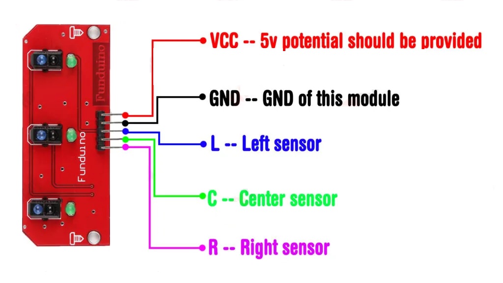
- VCC Power supply 5V
- GND Ground
- L Left sensor digital output
- C Center sensor digital output
- R Right sensor digital output
Applications
- Line follower robots
- Autonomous guided vehicles
- Sumo and mini sumo robots
- Industrial automation tracking
- Educational robotics projects
Example Circuit
Connect the sensor module to an Arduino board using the digital pins for L, C, and R. Supply the module with 5V and ground from the Arduino.

Library
No external libraries are required to use this module.
Arduino Code Example
#define left 6
#define center 7
#define right 8

#define ENA 9
#define IN1 2
#define IN2 3

#define ENB 10
#define IN3 4
#define IN4 5

int Speed = 120;

void setup() {
  Serial.begin(9600);

  pinMode(left, INPUT);
  pinMode(center, INPUT);
  pinMode(right, INPUT);

  pinMode(ENA, OUTPUT);
  pinMode(IN1, OUTPUT);
  pinMode(IN2, OUTPUT);
  pinMode(ENB, OUTPUT);
  pinMode(IN3, OUTPUT);
  pinMode(IN4, OUTPUT);
}

void loop() {
  bool leftV = digitalRead(left);
  bool centerV = digitalRead(center);
  bool rightV = digitalRead(right);

  if (leftV == 1 && centerV == 0 && rightV == 1) {
    carForward();
  } else if (leftV == 0 && centerV == 0 && rightV == 1) {
    carTurnLeft();
  } else if (leftV == 1 && centerV == 0 && rightV == 0) {
    carTurnRight();
  } else {
    carStop();
  }
}

void carForward() {
  analogWrite(ENA, Speed);
  analogWrite(ENB, Speed);
  digitalWrite(IN1, HIGH);
  digitalWrite(IN2, LOW);
  digitalWrite(IN3, HIGH);
  digitalWrite(IN4, LOW);
}

void carTurnLeft() {
  analogWrite(ENA, Speed);
  analogWrite(ENB, Speed);
  digitalWrite(IN1, LOW);
  digitalWrite(IN2, HIGH);
  digitalWrite(IN3, HIGH);
  digitalWrite(IN4, LOW);
}

void carTurnRight() {
  analogWrite(ENA, Speed);
  analogWrite(ENB, Speed);
  digitalWrite(IN1, HIGH);
  digitalWrite(IN2, LOW);
  digitalWrite(IN3, LOW);
  digitalWrite(IN4, HIGH);
}

void carStop() {
  digitalWrite(IN1, LOW);
  digitalWrite(IN2, LOW);
  digitalWrite(IN3, LOW);
  digitalWrite(IN4, LOW);
}
Technical Details
- Sensor type TCRT5000 reflective optical sensor
- Number of sensors 3
- Digital output
- Operating voltage 5V
- Size 118 mm x 80 mm x 10 mm
- Weight 11 g
Comparison
Compared to single channel IR sensors, the 3 channel TCRT5000 module offers higher accuracy and better stability. Multiple sensors allow detection of line position and direction, enabling smoother and more complex line following behavior.
Features
- Three infrared reflective sensors for accurate line tracking
- Detects black and white surface differences
- Digital output signals
- Low output on black surface and high output on white surface
- Operating voltage of 5V
- Compact design with fixed bolt hole
- Ideal for line follower and sumo robot projects
Principle of Operation
Each infrared sensor emits an IR beam toward the surface. Light surfaces reflect the beam back to the receiver, producing a high output. Dark surfaces absorb the light, resulting in a low output. By comparing the three outputs, a robot can determine the direction of the line and adjust its movement accordingly.
Pinout
- VCC Power supply 5V
- GND Ground
- L Left sensor digital output
- C Center sensor digital output
- R Right sensor digital output
Applications
- Line follower robots
- Autonomous guided vehicles
- Sumo and mini sumo robots
- Industrial automation tracking
- Educational robotics projects
Example Circuit
Connect the sensor module to an Arduino board using the digital pins for L, C, and R. Supply the module with 5V and ground from the Arduino.
Library
No external libraries are required to use this module.
Arduino Code Example
#define left 6
#define center 7
#define right 8

#define ENA 9
#define IN1 2
#define IN2 3

#define ENB 10
#define IN3 4
#define IN4 5

int Speed = 120;

void setup() {
  Serial.begin(9600);

  pinMode(left, INPUT);
  pinMode(center, INPUT);
  pinMode(right, INPUT);

  pinMode(ENA, OUTPUT);
  pinMode(IN1, OUTPUT);
  pinMode(IN2, OUTPUT);
  pinMode(ENB, OUTPUT);
  pinMode(IN3, OUTPUT);
  pinMode(IN4, OUTPUT);
}

void loop() {
  bool leftV = digitalRead(left);
  bool centerV = digitalRead(center);
  bool rightV = digitalRead(right);

  if (leftV == 1 && centerV == 0 && rightV == 1) {
    carForward();
  } else if (leftV == 0 && centerV == 0 && rightV == 1) {
    carTurnLeft();
  } else if (leftV == 1 && centerV == 0 && rightV == 0) {
    carTurnRight();
  } else {
    carStop();
  }
}

void carForward() {
  analogWrite(ENA, Speed);
  analogWrite(ENB, Speed);
  digitalWrite(IN1, HIGH);
  digitalWrite(IN2, LOW);
  digitalWrite(IN3, HIGH);
  digitalWrite(IN4, LOW);
}

void carTurnLeft() {
  analogWrite(ENA, Speed);
  analogWrite(ENB, Speed);
  digitalWrite(IN1, LOW);
  digitalWrite(IN2, HIGH);
  digitalWrite(IN3, HIGH);
  digitalWrite(IN4, LOW);
}

void carTurnRight() {
  analogWrite(ENA, Speed);
  analogWrite(ENB, Speed);
  digitalWrite(IN1, HIGH);
  digitalWrite(IN2, LOW);
  digitalWrite(IN3, LOW);
  digitalWrite(IN4, HIGH);
}

void carStop() {
  digitalWrite(IN1, LOW);
  digitalWrite(IN2, LOW);
  digitalWrite(IN3, LOW);
  digitalWrite(IN4, LOW);
}
Technical Details
- Sensor type TCRT5000 reflective optical sensor
- Number of sensors 3
- Digital output
- Operating voltage 5V
- Size 118 mm x 80 mm x 10 mm
- Weight 11 g
Comparison
Compared to single channel IR sensors, the 3 channel TCRT5000 module offers higher accuracy and better stability. Multiple sensors allow detection of line position and direction, enabling smoother and more complex line following behavior.