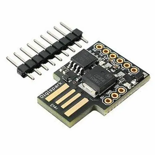
Digispark ATtiny85 USB REV3
The Digispark ATtiny85 USB REV3 is a compact development board based on the ATtiny85 microcontroller. It features USB connectivity, making it ideal for embedded projects with limited space. Despite its small size, it offers sufficient memory and I/O capabilities to support a wide range of applications. Compatible with the Arduino IDE, it offers an accessible development environment for beginners and advanced users alike.
Package Includes:
- 1 x Digispark ATtiny85 USB REV3
Features:
- ATtiny85 Microcontroller: 8KB flash memory, 512 bytes SRAM.
- USB Connectivity: Built-in USB interface eliminates the need for external programmers.
- Arduino Compatibility: Fully compatible with the Arduino IDE, supporting a wide range of libraries.
- I/O Pins: 6 general-purpose I/O pins for digital or analog use.
- Power Options: Powered via USB with a built-in voltage regulator (supports 5V–16V).
- Compact Size: Ideal for projects with space constraints.
- Low Cost: Budget-friendly for students, hobbyists, and professionals.
- Programmable: Easily programmable with the Arduino IDE and supported libraries.
- Standalone Operation: Operates independently without additional components.
- Open-Source: Design and schematics are open-source for customization.
Description:
The Digispark ATtiny85 USB REV3 is a compact development board based on the ATtiny85 microcontroller. It provides an affordable and flexible platform for USB-enabled embedded projects. Featuring 8KB of flash memory, 512 bytes of SRAM, and 6 I/O pins, it supports both digital and analog interfacing. With USB connectivity, Arduino IDE compatibility, and no need for an external power supply, it is perfect for a wide variety of small-scale and space-constrained applications.
Principle of Work:
- Microcontroller Operation: Runs user programs on the ATtiny85, utilizing flash and SRAM.
- USB Communication: Facilitates programming and device emulation via built-in USB.
- Programming: Uses Arduino IDE for code writing, compiling, and uploading over USB.
- Input/Output: 6 configurable I/O pins for digital/analog interfacing.
- Power Supply: Powered through USB; includes voltage regulator for 7–12V input.
- Arduino Compatibility: Seamlessly integrates into the Arduino ecosystem.
Pinout of the Module:

- P0: I2C SDA, PWM (onboard LED in older revisions)
- P1: PWM (onboard LED in Rev 2/3/4)
- P2: I2C SCK, analog input
- P3: Analog input, USB+
- P4: PWM, analog input, USB
- P5: Analog input, outputs 3V when HIGH
Other Pin Functions:
- Digital I/O: 6 pins (4 PWM capable), use with pinMode(), digitalWrite(), digitalRead()
- Analog Pins: 4 analog inputs
- GND: Ground
- AREF: Reference voltage for analog inputs (0–5V)
- SDA/SCL: I2C communication pins
- USB Connection: Emulated USB via V-USB library; requires driver
- On-Board LED: Connected to digital pin 0 (P0)
- Voltage Regulator: Converts 7–12V DC to 5V regulated output
- 5V Pin: Provides regulated 5V output
- Vin Pin: External power input (7–12V)
- Power LED Indicator: Shows board power status
Applications:
- Prototyping and DIY electronics projects
- Home automation systems
- Internet of Things (IoT)
- Small-scale robotics control
- Wearable electronics
- Educational programming and electronics courses
- Interactive art installations
- Sensor data logging
Circuit:
No external circuit required for basic testing. The built-in LED on pin P0 is used.
Library and Setup:
- Open Arduino IDE (download if needed).
- Connect the board to your computer via USB.
- Add Boards Manager URL:
- Go to File → Preferences → Additional Boards Manager URLs.
- Add:
http://digistump.com/package_digistump_index.json
- Install Board Support:
- Go to Tools → Board → Boards Manager.
- Search for “Digistump AVR Boards” and click Install.
- Install Windows Drivers:
- Download from: digistump.com
- Extract ZIP and run DPinst64.exe (64-bit) or DPinst.exe (32-bit)
- Approve any unsigned driver installation prompts
- Select Board:
- Tools → Board → Digispark (Default - 16.5mhz)
- Upload Code:
- Click upload in Arduino IDE.
- Wait for prompt to plug in board, then insert it.
- Code will upload and start automatically.
Sample Code:
// Pin declaration
const int LED_PIN = 0; // Pin P0

void setup() {
  pinMode(LED_PIN, OUTPUT); // Set LED_PIN as output
}

void loop() {
  digitalWrite(LED_PIN, HIGH); // Turn on LED
  delay(1000);                 // Wait 1 second
  digitalWrite(LED_PIN, LOW);  // Turn off LED
  delay(1000);                 // Wait 1 second
}
How the Code Works:
- Declares pin P0 as the LED pin.
- Sets the pin as OUTPUT in
setup(). - Turns LED on, delays 1s, then turns off and delays again inside
loop().
Technical Details:
- Microcontroller: ATtiny85
- Clock Speed: 16.5 MHz
- Operating Voltage: 5V
- DC Current on 5V Pin: 500mA
- Input Voltage (Recommended): 7V – 12V
- Output Voltage: 5V
- Digital I/O Pins: 6
- PWM Pins: 4
- Analog Input Pins: 4
Features:
- ATtiny85 Microcontroller: 8KB flash memory, 512 bytes SRAM.
- USB Connectivity: Built-in USB interface eliminates the need for external programmers.
- Arduino Compatibility: Fully compatible with the Arduino IDE, supporting a wide range of libraries.
- I/O Pins: 6 general-purpose I/O pins for digital or analog use.
- Power Options: Powered via USB with a built-in voltage regulator (supports 5V–16V).
- Compact Size: Ideal for projects with space constraints.
- Low Cost: Budget-friendly for students, hobbyists, and professionals.
- Programmable: Easily programmable with the Arduino IDE and supported libraries.
- Standalone Operation: Operates independently without additional components.
- Open-Source: Design and schematics are open-source for customization.
Description:
The Digispark ATtiny85 USB REV3 is a compact development board based on the ATtiny85 microcontroller. It provides an affordable and flexible platform for USB-enabled embedded projects. Featuring 8KB of flash memory, 512 bytes of SRAM, and 6 I/O pins, it supports both digital and analog interfacing. With USB connectivity, Arduino IDE compatibility, and no need for an external power supply, it is perfect for a wide variety of small-scale and space-constrained applications.
Principle of Work:
- Microcontroller Operation: Runs user programs on the ATtiny85, utilizing flash and SRAM.
- USB Communication: Facilitates programming and device emulation via built-in USB.
- Programming: Uses Arduino IDE for code writing, compiling, and uploading over USB.
- Input/Output: 6 configurable I/O pins for digital/analog interfacing.
- Power Supply: Powered through USB; includes voltage regulator for 7–12V input.
- Arduino Compatibility: Seamlessly integrates into the Arduino ecosystem.
Pinout of the Module:
- P0: I2C SDA, PWM (onboard LED in older revisions)
- P1: PWM (onboard LED in Rev 2/3/4)
- P2: I2C SCK, analog input
- P3: Analog input, USB+
- P4: PWM, analog input, USB
- P5: Analog input, outputs 3V when HIGH
Other Pin Functions:
- Digital I/O: 6 pins (4 PWM capable), use with pinMode(), digitalWrite(), digitalRead()
- Analog Pins: 4 analog inputs
- GND: Ground
- AREF: Reference voltage for analog inputs (0–5V)
- SDA/SCL: I2C communication pins
- USB Connection: Emulated USB via V-USB library; requires driver
- On-Board LED: Connected to digital pin 0 (P0)
- Voltage Regulator: Converts 7–12V DC to 5V regulated output
- 5V Pin: Provides regulated 5V output
- Vin Pin: External power input (7–12V)
- Power LED Indicator: Shows board power status
Applications:
- Prototyping and DIY electronics projects
- Home automation systems
- Internet of Things (IoT)
- Small-scale robotics control
- Wearable electronics
- Educational programming and electronics courses
- Interactive art installations
- Sensor data logging
Circuit:
No external circuit required for basic testing. The built-in LED on pin P0 is used.
Library and Setup:
- Open Arduino IDE (download if needed).
- Connect the board to your computer via USB.
- Add Boards Manager URL:
- Go to File → Preferences → Additional Boards Manager URLs.
- Add:
http://digistump.com/package_digistump_index.json
- Install Board Support:
- Go to Tools → Board → Boards Manager.
- Search for “Digistump AVR Boards” and click Install.
- Install Windows Drivers:
- Download from: digistump.com
- Extract ZIP and run DPinst64.exe (64-bit) or DPinst.exe (32-bit)
- Approve any unsigned driver installation prompts
- Select Board:
- Tools → Board → Digispark (Default - 16.5mhz)
- Upload Code:
- Click upload in Arduino IDE.
- Wait for prompt to plug in board, then insert it.
- Code will upload and start automatically.
Sample Code:
// Pin declaration
const int LED_PIN = 0; // Pin P0

void setup() {
  pinMode(LED_PIN, OUTPUT); // Set LED_PIN as output
}

void loop() {
  digitalWrite(LED_PIN, HIGH); // Turn on LED
  delay(1000);                 // Wait 1 second
  digitalWrite(LED_PIN, LOW);  // Turn off LED
  delay(1000);                 // Wait 1 second
}
How the Code Works:
- Declares pin P0 as the LED pin.
- Sets the pin as OUTPUT in
setup(). - Turns LED on, delays 1s, then turns off and delays again inside
loop().
Technical Details:
- Microcontroller: ATtiny85
- Clock Speed: 16.5 MHz
- Operating Voltage: 5V
- DC Current on 5V Pin: 500mA
- Input Voltage (Recommended): 7V – 12V
- Output Voltage: 5V
- Digital I/O Pins: 6
- PWM Pins: 4
- Analog Input Pins: 4