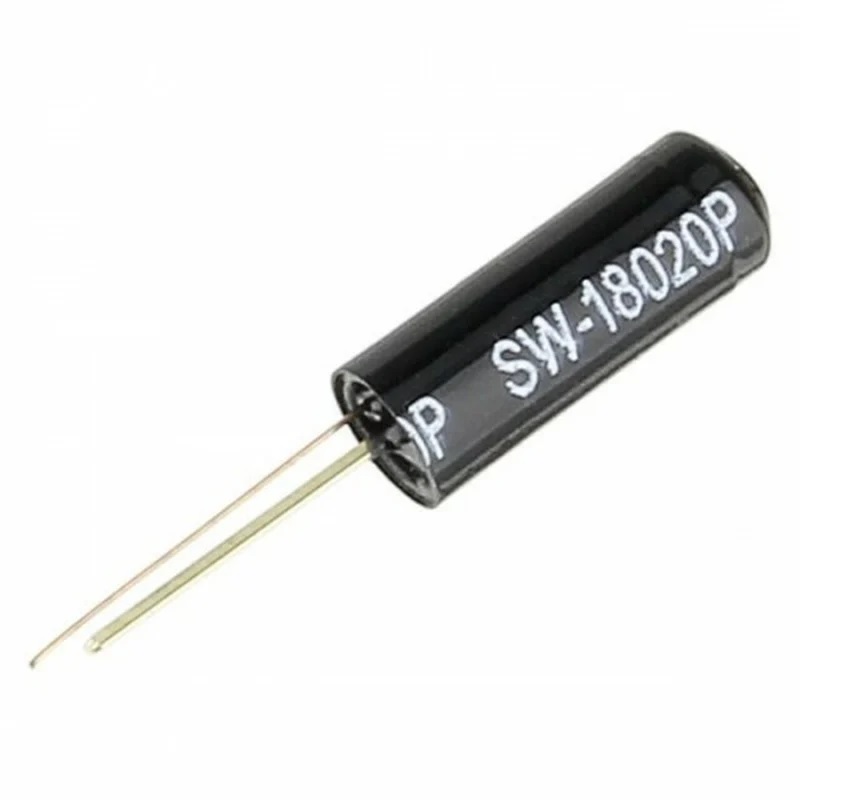
Tilt Shock Sensor SW-18020P
Tilt sensors are designed to detect orientation and inclination changes. They are compact, affordable, low power, and simple to use, making them a popular choice in toys, gadgets, and household appliances. When used properly, these sensors do not wear out and offer long-term reliability. Tilt sensors are commonly known as tilt switches, rolling ball sensors, or mercury switches. They work as simple on off switches that react to movement or angle changes, providing an easy way to detect motion or position.
Package Includes
- 1 x Tilt Shock Sensor SW-18020P
Features
- Operating voltage range from 3.3V to 5V
- TTL digital output
- Minimum current consumption of 25mA
- Easy to interface with microcontrollers
- Low cost and reliable performance
- High durability and long service life
Principle of Work
A typical ball tilt sensor consists of a metal tube containing a small rolling ball. Two conductive poles are placed at one end. With the correct orientation, the ball touches the poles and completes the circuit. When tilted beyond a certain angle, the ball moves away and the circuit opens.

Pinout
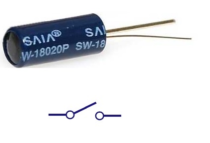
The tilt sensor works like a simple switch, so its two pins can be connected interchangeably.
Applications
- Robotics and automation systems
- Automotive safety and orientation detection
- Direction and movement detection
- Toys and interactive gadgets
- Appliance safety systems
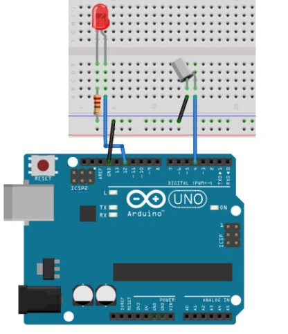
Example Circuit
Connect the tilt sensor to an Arduino UNO by attaching one pin of the sensor to digital pin 4 and the other pin to ground. Connect an LED to digital pin 12 through a 220 ohm resistor. When the sensor is tilted, the LED will turn on or off.
Library
No external library is required to use this module.
Arduino Code Example
int ledPin = 12;
int sensorPin = 4;
int sensorValue;
int lastTiltState = HIGH;

long lastDebounceTime = 0;
long debounceDelay = 50;

void setup() {
  pinMode(sensorPin, INPUT);
  digitalWrite(sensorPin, HIGH);
  pinMode(ledPin, OUTPUT);
  Serial.begin(9600);
}

void loop() {
  sensorValue = digitalRead(sensorPin);

  if (sensorValue == lastTiltState) {
    lastDebounceTime = millis();
  }

  if ((millis() - lastDebounceTime) > debounceDelay) {
    lastTiltState = sensorValue;
  }

  digitalWrite(ledPin, lastTiltState);
  Serial.println(sensorValue);
  delay(500);
}
Technical Details
- Maximum working voltage: 12V
- Maximum current: less than 5mA
- Open circuit resistance: more than 10 Mega Ohms
- On resistance: less than 5 ohms
- Response time: 2 ms
- Ambient temperature: less than 100 C
- Life expectancy: 500000 operations
Comparison
Switch-based tilt sensors provide only two output states, making them simple and reliable. Ball based tilt sensors use a metal ball instead of mercury and offer better resistance to vibration. Mercury tilt switches were among the earliest designs but are discouraged today due to mercury toxicity and safety concerns.
Features
- Operating voltage range from 3.3V to 5V
- TTL digital output
- Minimum current consumption of 25mA
- Easy to interface with microcontrollers
- Low cost and reliable performance
- High durability and long service life
Principle of Work
A typical ball tilt sensor consists of a metal tube containing a small rolling ball. Two conductive poles are placed at one end. With the correct orientation, the ball touches the poles and completes the circuit. When tilted beyond a certain angle, the ball moves away and the circuit opens.
Pinout
The tilt sensor works like a simple switch, so its two pins can be connected interchangeably.
Applications
- Robotics and automation systems
- Automotive safety and orientation detection
- Direction and movement detection
- Toys and interactive gadgets
- Appliance safety systems
Example Circuit
Connect the tilt sensor to an Arduino UNO by attaching one pin of the sensor to digital pin 4 and the other pin to ground. Connect an LED to digital pin 12 through a 220 ohm resistor. When the sensor is tilted, the LED will turn on or off.
Library
No external library is required to use this module.
Arduino Code Example
int ledPin = 12;
int sensorPin = 4;
int sensorValue;
int lastTiltState = HIGH;

long lastDebounceTime = 0;
long debounceDelay = 50;

void setup() {
  pinMode(sensorPin, INPUT);
  digitalWrite(sensorPin, HIGH);
  pinMode(ledPin, OUTPUT);
  Serial.begin(9600);
}

void loop() {
  sensorValue = digitalRead(sensorPin);

  if (sensorValue == lastTiltState) {
    lastDebounceTime = millis();
  }

  if ((millis() - lastDebounceTime) > debounceDelay) {
    lastTiltState = sensorValue;
  }

  digitalWrite(ledPin, lastTiltState);
  Serial.println(sensorValue);
  delay(500);
}
Technical Details
- Maximum working voltage: 12V
- Maximum current: less than 5mA
- Open circuit resistance: more than 10 Mega Ohms
- On resistance: less than 5 ohms
- Response time: 2 ms
- Ambient temperature: less than 100 C
- Life expectancy: 500000 operations
Comparison
Switch-based tilt sensors provide only two output states, making them simple and reliable. Ball based tilt sensors use a metal ball instead of mercury and offer better resistance to vibration. Mercury tilt switches were among the earliest designs but are discouraged today due to mercury toxicity and safety concerns.