- All products
- Development Boards
- Arduino
- Arduino Boards
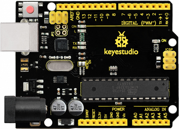
- Keyestudio UNO R3 Compatible with Arduino KS0001 (USB CABLE included)
- Arduino Boards
Features
- ATmega328P-based Arduino UNO R3-compatible development board.
- ATmega16U2 USB-to-serial interface for programming and serial communication.
- 14 digital input/output pins, including 6 PWM-capable pins.
- 6 analog input pins for reading analog sensors.
- 32 KB Flash memory for program storage.
- 2 KB SRAM for runtime data.
- 1 KB EEPROM for non-volatile data storage.
- 16 MHz clock frequency.
- Supports UART, SPI, and I2C communication.
- Standard UNO R3 shield-compatible form factor.
- Includes SDA, SCL, and IOREF pins for expanded compatibility.
- Enhanced reset circuit.
- Built-in power, TX/RX, and user LED indicators.
- Can be powered through USB, DC barrel jack, or external power input.
- Suitable for use with Arduino IDE and Arduino-compatible libraries.
- V pin switchable between 5V and 3.3V according to the supplied board description.
Principle of Operation
The Keyestudio UNO R3 uses the ATmega328P as its main microcontroller. Programs, known as sketches, are written using the Arduino IDE and uploaded to the board through the USB connection.
The onboard ATmega16U2 handles USB-to-serial communication between the computer and the ATmega328P. A bootloader stored in the ATmega328P allows new programs to be uploaded without requiring an external programmer.
Once programmed, the microcontroller executes the uploaded sketch and can read sensors through its analog and digital inputs, control actuators through its digital outputs and PWM pins, and communicate with external devices using UART, SPI, or I2C.
Applications
- Arduino learning and educational projects
- Embedded systems development
- Sensor and measurement projects
- Weighing machines and measurement systems
- Traffic light and countdown timer projects
- Parking lot counter systems
- Home automation
- Industrial automation prototypes
- Robotics projects
- LED and lighting control
- Motor and relay control
- Medical instrumentation prototypes
- Emergency lighting and control systems
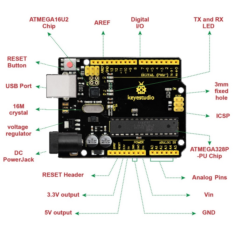
Pinout

| Pin / Interface | Description |
|---|---|
| D0–D13 | 14 digital I/O pins |
| D3, D5, D6, D9, D10, D11 | PWM-capable digital pins |
| A0–A5 | 6 analog input pins |
| A4 / SDA | I2C data line |
| A5 / SCL | I2C clock line |
| D0 / RX | UART receive pin |
| D1 / TX | UART transmit pin |
| D10 / SS | SPI slave-select pin |
| D11 / MOSI | SPI data output from Arduino |
| D12 / MISO | SPI data input to Arduino |
| D13 / SCK | SPI clock |
| AREF | Analog reference voltage |
| RESET | Resets the microcontroller |
| IOREF | Provides the board's I/O reference voltage to shields |
| 5V | 5V regulated supply |
| 3.3V | 3.3V supply output |
| GND | Ground connections |
Wiring
No external wiring is required to perform the basic first-time test because the board includes a built-in LED connected to digital pin 13. Connect the Keyestudio UNO R3 to a computer using the supplied USB cable and upload a Blink sketch.
| Connection | Purpose |
|---|---|
| USB | Programming, serial communication, and USB power |
| D13 LED | Built-in LED for testing digital output |
Getting Started for the First Time
- Download and install the Arduino IDE.
- Connect the Keyestudio UNO R3 to the computer using the supplied USB data cable.
- Open the Arduino IDE.
- Go to Tools → Board and select Arduino Uno.
- Go to Tools → Port and select the COM port assigned to the board.
- Open File → Examples → 01.Basics → Blink.
- Click Verify to compile the sketch.
- Click Upload to program the board.
- After the upload is complete, the onboard LED connected to D13 should blink approximately once per second.
Arduino Example
void setup() {
pinMode(13, OUTPUT);
}
void loop() {
digitalWrite(13, HIGH);
delay(1000);
digitalWrite(13, LOW);
delay(1000);
}
Specifications
| Product Name | Keyestudio UNO R3 Compatible Development Board |
| Model | KS0001 |
| Main Microcontroller | ATmega328P |
| USB-to-Serial Controller | ATmega16U2 |
| Operating Voltage | 5V |
| Input Voltage Recommended | 7–12V |
| Input Voltage Limit | 7–20V |
| Digital I/O Pins | 14 |
| PWM Pins | 6 |
| Analog Inputs | 6 |
| Flash Memory | 32 KB, including 0.5 KB bootloader |
| SRAM | 2 KB |
| EEPROM | 1 KB |
| Clock Frequency | 16 MHz |
| DC Current per I/O Pin | 20 mA |
| 3.3V Pin Current | 50 mA |
| Communication | UART, SPI, I2C |
| Board Length | 68.6 mm |
| Board Width | 53.4 mm |
| Weight | Approximately 25 g |
Keyestudio UNO R3 vs. Arduino UNO R3
The Keyestudio UNO R3 is designed to be functionally compatible with the standard Arduino UNO R3 and uses the same ATmega328P-based architecture, pin arrangement, 16 MHz operating frequency, memory configuration, and Arduino IDE programming workflow.
The supplied board additionally features a 5V/3.3V selectable voltage switch, providing additional flexibility when working with compatible shields and modules requiring different logic or supply voltages.
Resources
Features
- ATmega328P-based Arduino UNO R3-compatible development board.
- ATmega16U2 USB-to-serial interface for programming and serial communication.
- 14 digital input/output pins, including 6 PWM-capable pins.
- 6 analog input pins for reading analog sensors.
- 32 KB Flash memory for program storage.
- 2 KB SRAM for runtime data.
- 1 KB EEPROM for non-volatile data storage.
- 16 MHz clock frequency.
- Supports UART, SPI, and I2C communication.
- Standard UNO R3 shield-compatible form factor.
- Includes SDA, SCL, and IOREF pins for expanded compatibility.
- Enhanced reset circuit.
- Built-in power, TX/RX, and user LED indicators.
- Can be powered through USB, DC barrel jack, or external power input.
- Suitable for use with Arduino IDE and Arduino-compatible libraries.
- V pin switchable between 5V and 3.3V according to the supplied board description.
Principle of Operation
The Keyestudio UNO R3 uses the ATmega328P as its main microcontroller. Programs, known as sketches, are written using the Arduino IDE and uploaded to the board through the USB connection.
The onboard ATmega16U2 handles USB-to-serial communication between the computer and the ATmega328P. A bootloader stored in the ATmega328P allows new programs to be uploaded without requiring an external programmer.
Once programmed, the microcontroller executes the uploaded sketch and can read sensors through its analog and digital inputs, control actuators through its digital outputs and PWM pins, and communicate with external devices using UART, SPI, or I2C.
Applications
- Arduino learning and educational projects
- Embedded systems development
- Sensor and measurement projects
- Weighing machines and measurement systems
- Traffic light and countdown timer projects
- Parking lot counter systems
- Home automation
- Industrial automation prototypes
- Robotics projects
- LED and lighting control
- Motor and relay control
- Medical instrumentation prototypes
- Emergency lighting and control systems
Pinout

| Pin / Interface | Description |
|---|---|
| D0–D13 | 14 digital I/O pins |
| D3, D5, D6, D9, D10, D11 | PWM-capable digital pins |
| A0–A5 | 6 analog input pins |
| A4 / SDA | I2C data line |
| A5 / SCL | I2C clock line |
| D0 / RX | UART receive pin |
| D1 / TX | UART transmit pin |
| D10 / SS | SPI slave-select pin |
| D11 / MOSI | SPI data output from Arduino |
| D12 / MISO | SPI data input to Arduino |
| D13 / SCK | SPI clock |
| AREF | Analog reference voltage |
| RESET | Resets the microcontroller |
| IOREF | Provides the board's I/O reference voltage to shields |
| 5V | 5V regulated supply |
| 3.3V | 3.3V supply output |
| GND | Ground connections |
Wiring
No external wiring is required to perform the basic first-time test because the board includes a built-in LED connected to digital pin 13. Connect the Keyestudio UNO R3 to a computer using the supplied USB cable and upload a Blink sketch.
| Connection | Purpose |
|---|---|
| USB | Programming, serial communication, and USB power |
| D13 LED | Built-in LED for testing digital output |
Getting Started for the First Time
- Download and install the Arduino IDE.
- Connect the Keyestudio UNO R3 to the computer using the supplied USB data cable.
- Open the Arduino IDE.
- Go to Tools → Board and select Arduino Uno.
- Go to Tools → Port and select the COM port assigned to the board.
- Open File → Examples → 01.Basics → Blink.
- Click Verify to compile the sketch.
- Click Upload to program the board.
- After the upload is complete, the onboard LED connected to D13 should blink approximately once per second.
Arduino Example
void setup() {
pinMode(13, OUTPUT);
}
void loop() {
digitalWrite(13, HIGH);
delay(1000);
digitalWrite(13, LOW);
delay(1000);
}Specifications
| Product Name | Keyestudio UNO R3 Compatible Development Board |
| Model | KS0001 |
| Main Microcontroller | ATmega328P |
| USB-to-Serial Controller | ATmega16U2 |
| Operating Voltage | 5V |
| Input Voltage Recommended | 7–12V |
| Input Voltage Limit | 7–20V |
| Digital I/O Pins | 14 |
| PWM Pins | 6 |
| Analog Inputs | 6 |
| Flash Memory | 32 KB, including 0.5 KB bootloader |
| SRAM | 2 KB |
| EEPROM | 1 KB |
| Clock Frequency | 16 MHz |
| DC Current per I/O Pin | 20 mA |
| 3.3V Pin Current | 50 mA |
| Communication | UART, SPI, I2C |
| Board Length | 68.6 mm |
| Board Width | 53.4 mm |
| Weight | Approximately 25 g |
Keyestudio UNO R3 vs. Arduino UNO R3
The Keyestudio UNO R3 is designed to be functionally compatible with the standard Arduino UNO R3 and uses the same ATmega328P-based architecture, pin arrangement, 16 MHz operating frequency, memory configuration, and Arduino IDE programming workflow.
The supplied board additionally features a 5V/3.3V selectable voltage switch, providing additional flexibility when working with compatible shields and modules requiring different logic or supply voltages.
Resources