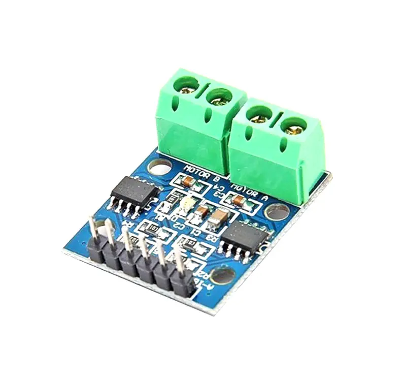
Motor Driver Module 2Ch 0.8 12V HG7881- L9110S
The HG7881 is a two-channel motor driver module that provides bi-directional control for two DC motors. It can handle a maximum voltage of 12V and a current of 0.8A per channel, which is suitable for small to medium-sized motors. The module uses pulse width modulation (PWM) to control the speed of each motor, which means that the motors can be run at varying speeds. It also allows for independent control of the direction of each motor, so both motors can be run in forward or reverse directions. The module can be controlled by a microcontroller, such as an Arduino or Raspberry Pi, through its input pins. It has two sets of input pins, one for each motor channel, which includes pins for controlling the direction and speed of each motor. In addition, the HG7881 has built-in protection features such as overcurrent protection and thermal shutdown, which help to prevent damage to the module and the connected motors. The overcurrent protection kicks in if the current drawn by the motor exceeds the maximum current limit, while the thermal shutdown is triggered when the temperature of the module reaches a certain level.
Package Includes:
- 1 x Motor Driver Module 2ch 0.8 12V HG7881- L9110S
Features:
- Two-channel motor control: The HG7881 can control two DC motors independently, providing bi-directional control for each motor.
- The maximum voltage of 12V: The module can handle a maximum voltage of 12V, which is suitable for small to medium-sized motors.
- The current limit of 0.8A per channel: The module can handle a maximum current of 0.8A per channel, which is suitable for small to medium-sized motors.
- Pulse Width Modulation (PWM) control: The module uses PWM to control the speed of each motor, allowing for varying speeds.
- Independent motor direction control: The module allows for independent control of the direction of each motor, so both motors can be run in forward or reverse directions.
- Input pins for control: The module can be controlled by a microcontroller through its input pins, which include pins for controlling the direction and speed of each motor.
- Built-in protection features: The HG7881 has built-in overcurrent protection and thermal shutdown features to prevent damage to the module and the connected motors.
- Easy to use: The module is easy to use and can be integrated into various projects that require motor control, such as robotics and automation.
Principle of Work:
The HG7881 motor driver module works based on the H-bridge configuration, which allows it to provide bi-directional control for two DC motors. Each channel of the module consists of four transistors (two NPN and two PNP) that are arranged in an H-bridge configuration. The transistors are used to switch the direction of the current flowing through the motor, which allows for bi-directional control. The speed of the motor is controlled using Pulse Width Modulation (PWM) signals. The PWM signal is applied to the input pins of the module, which then controls the ON/OFF time of the transistors in the H-bridge. This results in a varying voltage that is applied to the motor, which in turn controls the speed of the motor. The module also includes built-in protection features such as overcurrent protection and thermal shutdown. The overcurrent protection feature monitors the current flowing through the motor and triggers a shutdown if the current exceeds the maximum limit. The thermal shutdown feature monitors the temperature of the module and shuts down if the temperature exceeds a certain level. These protection features help to prevent damage to the module and the connected motors.
Pinout of the Module:

| Pin | Function | Description |
|---|---|---|
| VCC | Power Supply | Powers the module. Requires 2.5V to 12V DC input voltage. |
| GND | Ground | Connected to the ground of the power supply. |
| Input 1A | Motor 1 Direction Control | Controls the direction of motor 1. Logic high for one direction, logic low for the opposite direction. |
| Input 1B | Motor 1 Speed Control | Controls the speed of motor 1. PWM signal applied to adjust speed. |
| Input 2A | Motor 2 Direction Control | Controls the direction of motor 2. Logic high for one direction, logic low for the opposite direction. |
| Input 2B | Motor 2 Speed Control | Controls the speed of motor 2. PWM signal applied to adjust speed. |
| Out A 1-2 | Output for Motor 1 | Output pin for motor 1. |
| Out B 1-2 | Output for Motor 2 | Output pin for motor 2. |
Applications:
- Robotics: Control robot arms, wheels, and other components.
- Automation: Drive conveyor belts, robotic arms, and machinery.
- Remote Control Cars and Drones: Manage wheel and propeller motors.
- Motorized Blinds and Curtains: Open and close blinds or curtains.
- Fans and Ventilation Systems: Adjust fan speeds.
- DIY Projects: Motorized camera sliders, gates, and more.
Circuit:

- Connect the positive wire of the motor to the motor "A" connector on the left of the HG7881 module and the negative wire to the connector on the right.
- Connect a power supply with a voltage range between 3 to 12V DC depending on the motor you use to the VCC and GND pins of the module.
- Connect the ground pin of the power supply to the GND pin of the module.
- Connect any two digital output pins on the Arduino board to the A1A and A1B pins on the HG7881 module for direction control (we will use pins 2 and 3 in the example).
- If the motor spins in the opposite direction of what you wanted, swap the motor wires connected to the "A" connector.
Library:
No library needed.
Code:
This example code allows controlling the motor direction using the Serial Monitor. Commands:
- Send 'f' to turn the motor forward.
- Send 'r' to turn the motor in reverse.
- Send any other character to stop the motor.
const int A1A = 3;
const int A1B = 2;

void setup() {
  pinMode(A1A, OUTPUT);
  pinMode(A1B, OUTPUT);
  Serial.begin(9600);
}

void loop() {
  if (Serial.available()) {
    char command = Serial.read();
    if (command == 'f') {
      digitalWrite(A1A, HIGH);
      digitalWrite(A1B, LOW);
    } else if (command == 'r') {
      digitalWrite(A1A, LOW);
      digitalWrite(A1B, HIGH);
    } else {
      digitalWrite(A1A, LOW);
      digitalWrite(A1B, LOW);
    }
  }
}
Technical Details:
- Low standby current: less than 1mA
- Control interface: 2 logic-level inputs per channel
- Reverse voltage protection
- Over-temperature protection
- Input voltage: 2.5-12V DC
- Each channel has a continuous output current of 800 mA
- PCB Size: 29.2mm x 23mm
Comparisons:
Both the HG7881-L9110S and the L293D are popular motor driver modules, each with its own characteristics:
- Operating Voltage: The HG7881 supports up to 12V, suitable for low to medium voltage motors. The L293D supports up to 36V.
- Current Capacity: HG7881 supports up to 0.8A per channel continuous, L293D supports 600mA continuous per channel (peak 1.2A).
- Heat Dissipation: Both need heat sinks for high current but HG7881 tends to have lower power dissipation.
- Package Size: HG7881 module is compact (29.2mm x 23mm), whereas L293D IC is a DIP package.
- Features: HG7881 is simpler and easier to use for small projects; L293D is more versatile with higher voltage and current tolerance.
Features:
- Two-channel motor control: The HG7881 can control two DC motors independently, providing bi-directional control for each motor.
- The maximum voltage of 12V: The module can handle a maximum voltage of 12V, which is suitable for small to medium-sized motors.
- The current limit of 0.8A per channel: The module can handle a maximum current of 0.8A per channel, which is suitable for small to medium-sized motors.
- Pulse Width Modulation (PWM) control: The module uses PWM to control the speed of each motor, allowing for varying speeds.
- Independent motor direction control: The module allows for independent control of the direction of each motor, so both motors can be run in forward or reverse directions.
- Input pins for control: The module can be controlled by a microcontroller through its input pins, which include pins for controlling the direction and speed of each motor.
- Built-in protection features: The HG7881 has built-in overcurrent protection and thermal shutdown features to prevent damage to the module and the connected motors.
- Easy to use: The module is easy to use and can be integrated into various projects that require motor control, such as robotics and automation.
Principle of Work:
The HG7881 motor driver module works based on the H-bridge configuration, which allows it to provide bi-directional control for two DC motors. Each channel of the module consists of four transistors (two NPN and two PNP) that are arranged in an H-bridge configuration. The transistors are used to switch the direction of the current flowing through the motor, which allows for bi-directional control. The speed of the motor is controlled using Pulse Width Modulation (PWM) signals. The PWM signal is applied to the input pins of the module, which then controls the ON/OFF time of the transistors in the H-bridge. This results in a varying voltage that is applied to the motor, which in turn controls the speed of the motor. The module also includes built-in protection features such as overcurrent protection and thermal shutdown. The overcurrent protection feature monitors the current flowing through the motor and triggers a shutdown if the current exceeds the maximum limit. The thermal shutdown feature monitors the temperature of the module and shuts down if the temperature exceeds a certain level. These protection features help to prevent damage to the module and the connected motors.
Pinout of the Module:
| Pin | Function | Description |
|---|---|---|
| VCC | Power Supply | Powers the module. Requires 2.5V to 12V DC input voltage. |
| GND | Ground | Connected to the ground of the power supply. |
| Input 1A | Motor 1 Direction Control | Controls the direction of motor 1. Logic high for one direction, logic low for the opposite direction. |
| Input 1B | Motor 1 Speed Control | Controls the speed of motor 1. PWM signal applied to adjust speed. |
| Input 2A | Motor 2 Direction Control | Controls the direction of motor 2. Logic high for one direction, logic low for the opposite direction. |
| Input 2B | Motor 2 Speed Control | Controls the speed of motor 2. PWM signal applied to adjust speed. |
| Out A 1-2 | Output for Motor 1 | Output pin for motor 1. |
| Out B 1-2 | Output for Motor 2 | Output pin for motor 2. |
Applications:
- Robotics: Control robot arms, wheels, and other components.
- Automation: Drive conveyor belts, robotic arms, and machinery.
- Remote Control Cars and Drones: Manage wheel and propeller motors.
- Motorized Blinds and Curtains: Open and close blinds or curtains.
- Fans and Ventilation Systems: Adjust fan speeds.
- DIY Projects: Motorized camera sliders, gates, and more.
Circuit:
- Connect the positive wire of the motor to the motor "A" connector on the left of the HG7881 module and the negative wire to the connector on the right.
- Connect a power supply with a voltage range between 3 to 12V DC depending on the motor you use to the VCC and GND pins of the module.
- Connect the ground pin of the power supply to the GND pin of the module.
- Connect any two digital output pins on the Arduino board to the A1A and A1B pins on the HG7881 module for direction control (we will use pins 2 and 3 in the example).
- If the motor spins in the opposite direction of what you wanted, swap the motor wires connected to the "A" connector.
Library:
No library needed.
Code:
This example code allows controlling the motor direction using the Serial Monitor. Commands:
- Send 'f' to turn the motor forward.
- Send 'r' to turn the motor in reverse.
- Send any other character to stop the motor.
const int A1A = 3;
const int A1B = 2;

void setup() {
  pinMode(A1A, OUTPUT);
  pinMode(A1B, OUTPUT);
  Serial.begin(9600);
}

void loop() {
  if (Serial.available()) {
    char command = Serial.read();
    if (command == 'f') {
      digitalWrite(A1A, HIGH);
      digitalWrite(A1B, LOW);
    } else if (command == 'r') {
      digitalWrite(A1A, LOW);
      digitalWrite(A1B, HIGH);
    } else {
      digitalWrite(A1A, LOW);
      digitalWrite(A1B, LOW);
    }
  }
}
Technical Details:
- Low standby current: less than 1mA
- Control interface: 2 logic-level inputs per channel
- Reverse voltage protection
- Over-temperature protection
- Input voltage: 2.5-12V DC
- Each channel has a continuous output current of 800 mA
- PCB Size: 29.2mm x 23mm
Comparisons:
Both the HG7881-L9110S and the L293D are popular motor driver modules, each with its own characteristics:
- Operating Voltage: The HG7881 supports up to 12V, suitable for low to medium voltage motors. The L293D supports up to 36V.
- Current Capacity: HG7881 supports up to 0.8A per channel continuous, L293D supports 600mA continuous per channel (peak 1.2A).
- Heat Dissipation: Both need heat sinks for high current but HG7881 tends to have lower power dissipation.
- Package Size: HG7881 module is compact (29.2mm x 23mm), whereas L293D IC is a DIP package.
- Features: HG7881 is simpler and easier to use for small projects; L293D is more versatile with higher voltage and current tolerance.