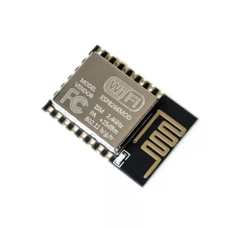
ESP8266 ESP-12E WiFi Module
The ESP8266 WiFi Module is a System-on-Chip (SoC) that includes an integrated TCP/IP protocol stack, enabling WiFi connectivity for any microcontroller. It can host an application or offload WiFi networking functions from another processor. Pre-programmed with an AT command firmware, it provides easy integration with Arduino, similar to a WiFi shield. Its low cost and broad community support make it ideal for IoT applications.
Package Includes:
- 1 x ESP8266 ESP-12E WiFi Module
Features:
- 802.11 b/g/n Support: Compatible with most wireless networks, both old and new.
- Low-Power 32-bit MCU: Efficient microcontroller core suitable for battery-powered applications.
- 10-bit ADC: Built-in analog-to-digital converter for sensor integration.
- Integrated TCP/IP Stack: Supports reliable communication over LAN or the internet.
- Compact Integrated Design: Includes TR switch, balun, LNA, PA, PLL, regulators, and PMU.
- Antenna Diversity: Improves signal reception in challenging environments.
- WPA/WPA2 Support: Ensures secure wireless communication.
- Multiple Operation Modes: Supports Station, Access Point, and mixed modes.
- Rich Interfaces: Includes UART, SPI, I2C, I2S, IRDA, PWM, GPIO, and SDIO.
Specifications:
- Supply Voltage: 3.3V
- Operating Temperature: -40°C to 125°C
- Deep Sleep Power: <10μA
- Leakage Current (Power Down): <5μA
- Wake & Transmit Time: <2ms
- Standby Power (DTIM3): <1.0mW
- Output Power (802.11b): +20dBm
Tutorial: Minimal Configuration for Running the ESP-12E Module
1. Understanding the ESP-12E Module
The ESP-12E features multiple GPIOs and 4MB flash memory.
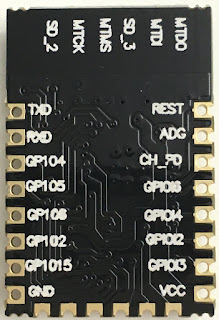
Image: ESP-12E Module
2. Module Notes
- Silkscreen might be poor quality.
- ADC pin is marked as ADG.
- GPIO0 may appear as GPIO6.
3. Basic Configuration
Essential setup to run the module:
- GPIO15 → GND
- CH_PD → 3.3V
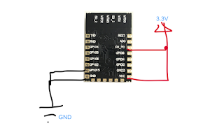
Image: Basic Configuration for ESP-12E
4. Flashing Firmware
To enter flashing mode:
- GPIO0 (GPIO6) → GND
- Use NodeMCU firmware for simplicity

Image: Flashing Firmware
5. Physical Connections
Using a USB-to-Serial converter:
- RXD ↔ TXD
- TXD ↔ RXD
- GND ↔ GND
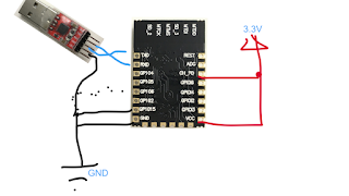
Image: Physical Connection
Features:
- 802.11 b/g/n Support: Compatible with most wireless networks, both old and new.
- Low-Power 32-bit MCU: Efficient microcontroller core suitable for battery-powered applications.
- 10-bit ADC: Built-in analog-to-digital converter for sensor integration.
- Integrated TCP/IP Stack: Supports reliable communication over LAN or the internet.
- Compact Integrated Design: Includes TR switch, balun, LNA, PA, PLL, regulators, and PMU.
- Antenna Diversity: Improves signal reception in challenging environments.
- WPA/WPA2 Support: Ensures secure wireless communication.
- Multiple Operation Modes: Supports Station, Access Point, and mixed modes.
- Rich Interfaces: Includes UART, SPI, I2C, I2S, IRDA, PWM, GPIO, and SDIO.
Specifications:
- Supply Voltage: 3.3V
- Operating Temperature: -40°C to 125°C
- Deep Sleep Power: <10μA
- Leakage Current (Power Down): <5μA
- Wake & Transmit Time: <2ms
- Standby Power (DTIM3): <1.0mW
- Output Power (802.11b): +20dBm
Tutorial: Minimal Configuration for Running the ESP-12E Module
1. Understanding the ESP-12E Module
The ESP-12E features multiple GPIOs and 4MB flash memory.
Image: ESP-12E Module
2. Module Notes
- Silkscreen might be poor quality.
- ADC pin is marked as ADG.
- GPIO0 may appear as GPIO6.
3. Basic Configuration
Essential setup to run the module:
- GPIO15 → GND
- CH_PD → 3.3V
Image: Basic Configuration for ESP-12E
4. Flashing Firmware
To enter flashing mode:
- GPIO0 (GPIO6) → GND
- Use NodeMCU firmware for simplicity
Image: Flashing Firmware
5. Physical Connections
Using a USB-to-Serial converter:
- RXD ↔ TXD
- TXD ↔ RXD
- GND ↔ GND
Image: Physical Connection