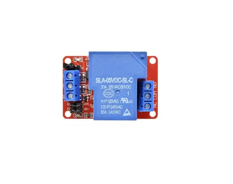
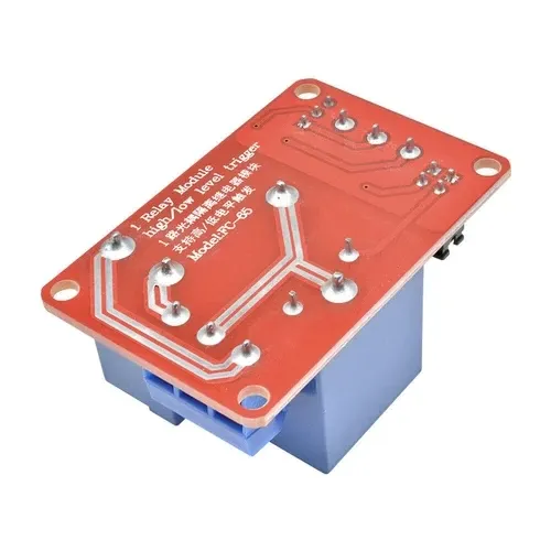


Features:
- 30A relay module, normally open interface, maximum load: AC 250V/30A, DV 30V/30A.
- Optical coupling isolation, driving ability is strong, and stable performance;The
- trigger current is ~5mA.
- The module can be set to a high-level or low-level trigger by the jumper.
- Power indicator light (green), relay status indicator light (red).
- Module Size:50mm*33mm*24mm.
Principle of Work:
A relay is a type of switch that can be controlled with an electrical signal. It is a way to open or close a circuit, in this case via a signal from the connected microcontroller. The relay isolates the circuit on the device you want to control from the device that's controlling it. And its High/Low Trigger, configured through a jumper, 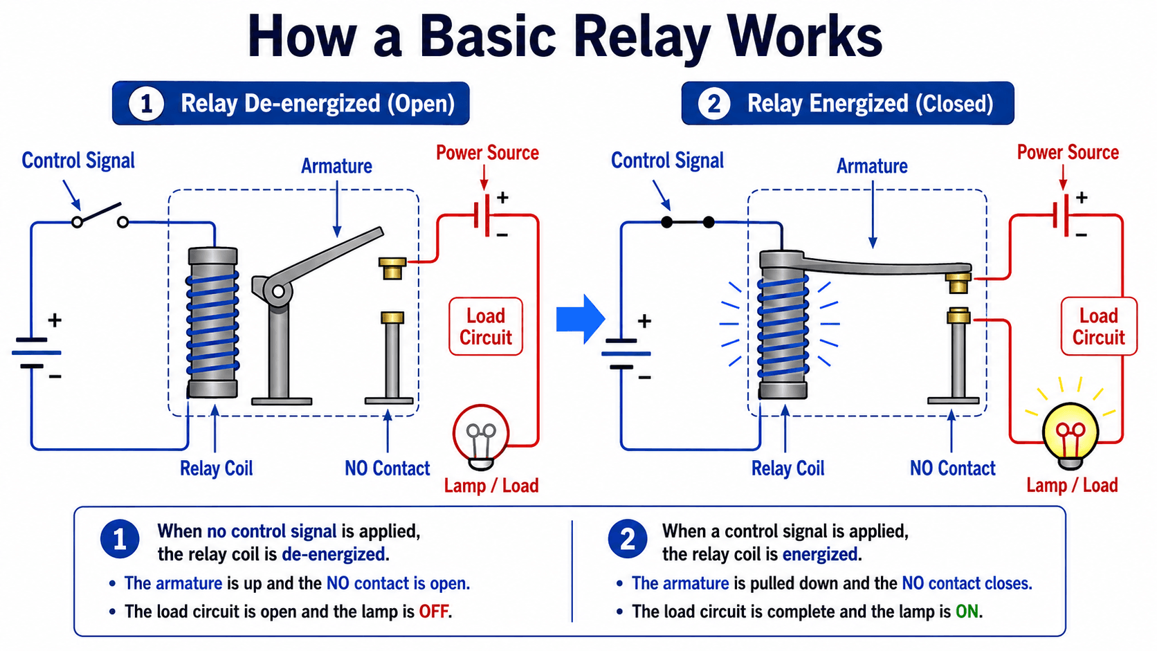
will allow the current to go through the power line when the control signal is VCC or High/GND or LOW when the jumper is changed. optocoupler, on the other hand makes real photo isolation between the relay and the MCU, which is very good to minimize distortion from the other side
Pinout of the Module:

- DC+: DC power supply positive pole
- DC-: DC power supply negative pole
- IN: signal triggering pin
- JD+: relay control voltage positive
- JD-: relay control voltage negative
- DC+ and JD+ shorted by jumper cap, DC- and JD- shorted with jumper cap, it is the same voltage between trigger terminal and relay control terminal
- High and low-level trigger mode selection. The jumper and L pin connection, IN pin, is a low-level trigger upper and H pin connection, IN pin, is a high-level trigger
- Normally closed pin (NC): relay normally closed pin
- Common pin (COM): relay common pin
- Normally opened pin (NO): relay normally opened pin
Applications:
- Relay Drive from External Contacts.
- LED Series and Parallel Connections.
- Electronic Circuit Drive by Means of a Relay.
- Home automation
- Battery backup
- High current load switching
Circuit:
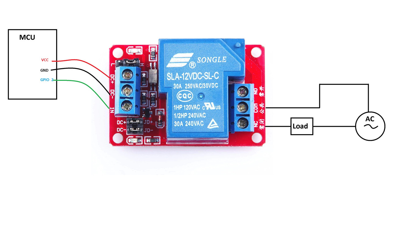
1 distinct load has been connected to the relay's NO terminals. the relay common terminal has a live wire connected to it. When the relay is activated, the load is powered and connected to the live wire. This configuration can be reversed by connecting the load to the NC terminal, which keeps the load powered on until the relay is activated. the relay is connected to pin 2 and the trigger in a high configuration.
Library:
This Module doesn't need a library to work.
Code:
void setup() {
 // initialize digital pin 2 as an output.
 pinMode(2, OUTPUT);


}
// the loop function runs over and over again forever
void loop() {
 digitalWrite(2, HIGH); // turn the LED ON by making the voltage HIGH delay(1000);
 delay(1000); // wait for a second


 digitalWrite(2, LOW); // turn the on off(LOW is the voltage level)
 delay(1000); // wait for a second


}
Technical Details:
- 1 Channel
- Voltage version: 5V
- The static current:5mA
- Working current:80mA
- Trigger current:2-4mA
Resources:
Features:
- 30A relay module, normally open interface, maximum load: AC 250V/30A, DV 30V/30A.
- Optical coupling isolation, driving ability is strong, and stable performance;The
- trigger current is ~5mA.
- The module can be set to a high-level or low-level trigger by the jumper.
- Power indicator light (green), relay status indicator light (red).
- Module Size:50mm*33mm*24mm.
Principle of Work:
A relay is a type of switch that can be controlled with an electrical signal. It is a way to open or close a circuit, in this case via a signal from the connected microcontroller. The relay isolates the circuit on the device you want to control from the device that's controlling it. And its High/Low Trigger, configured through a jumper,
will allow the current to go through the power line when the control signal is VCC or High/GND or LOW when the jumper is changed. optocoupler, on the other hand makes real photo isolation between the relay and the MCU, which is very good to minimize distortion from the other side
Pinout of the Module:
- DC+: DC power supply positive pole
- DC-: DC power supply negative pole
- IN: signal triggering pin
- JD+: relay control voltage positive
- JD-: relay control voltage negative
- DC+ and JD+ shorted by jumper cap, DC- and JD- shorted with jumper cap, it is the same voltage between trigger terminal and relay control terminal
- High and low-level trigger mode selection. The jumper and L pin connection, IN pin, is a low-level trigger upper and H pin connection, IN pin, is a high-level trigger
- Normally closed pin (NC): relay normally closed pin
- Common pin (COM): relay common pin
- Normally opened pin (NO): relay normally opened pin
Applications:
- Relay Drive from External Contacts.
- LED Series and Parallel Connections.
- Electronic Circuit Drive by Means of a Relay.
- Home automation
- Battery backup
- High current load switching
Circuit:
1 distinct load has been connected to the relay's NO terminals. the relay common terminal has a live wire connected to it. When the relay is activated, the load is powered and connected to the live wire. This configuration can be reversed by connecting the load to the NC terminal, which keeps the load powered on until the relay is activated. the relay is connected to pin 2 and the trigger in a high configuration.
Library:
This Module doesn't need a library to work.
Code:
void setup() {
 // initialize digital pin 2 as an output.
 pinMode(2, OUTPUT);


}
// the loop function runs over and over again forever
void loop() {
 digitalWrite(2, HIGH); // turn the LED ON by making the voltage HIGH delay(1000);
 delay(1000); // wait for a second


 digitalWrite(2, LOW); // turn the on off(LOW is the voltage level)
 delay(1000); // wait for a second


}
Technical Details:
- 1 Channel
- Voltage version: 5V
- The static current:5mA
- Working current:80mA
- Trigger current:2-4mA
Resources: