Features
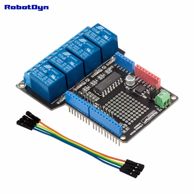
- Four relay channels: Independently control up to four electrical loads.
- High load switching capability: Suitable for switching AC and DC loads within the specified relay ratings.
- Optocoupler isolation: Uses a TLP521-4 four-channel optocoupler for electrical isolation between control and relay circuits.
- Arduino compatible: Designed for Arduino UNO and compatible development boards.
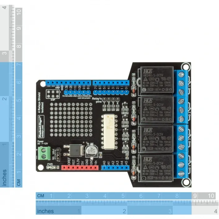
- Configurable control pins: Relay input channels can be assigned to Arduino digital pins through jumpers.
- Individual LED indicators: Provide visual indication of the activation status of each relay channel.
- Accessible relay terminals: Screw terminals are positioned for convenient load wiring.
- Reinforced power tracks: Additional solder reinforcement on power traces improves current-handling capability.
- Flexible power configuration: Jumper selection allows relay power to be supplied from the Arduino VIN connection or an external source.
- Expansion area: Additional soldering space is available for custom circuitry or modifications.
Principle of Operation
Each relay channel is controlled by a digital signal from the connected Arduino or microcontroller. When a relay input is activated, the corresponding optocoupler transfers the control signal across an isolation barrier to the relay driver circuit.

The relay then changes the state of its mechanical contacts, allowing an external load to be connected or disconnected. Each relay provides COM, NO, and NC terminals, allowing the load circuit to be configured as normally open or normally closed.
The optocoupler provides electrical separation between the low-voltage control circuitry and the relay-driving section. However, the relay contact terminals themselves must still be treated as potentially hazardous when connected to high-voltage AC sources.
Applications
- Home automation systems
- Arduino-controlled appliances
- AC and DC load switching
- Motor and pump control
- Solenoid valve control
- Lighting control systems
- Industrial automation prototypes
- Embedded control systems
- IoT switching applications
- Educational and electronics projects
Pinout
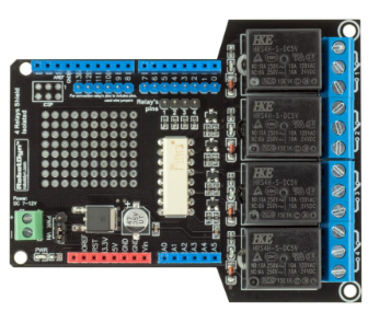
| Pin / Terminal | Function |
|---|---|
| GND | Ground connection for the control/power circuit |
| VCC | Relay supply input |
| IN1 | Relay Channel 1 control input |
| IN2 | Relay Channel 2 control input |
| IN3 | Relay Channel 3 control input |
| IN4 | Relay Channel 4 control input |
| COM | Common relay contact |
| NO | Normally Open contact |
| NC | Normally Closed contact |
Wiring
The shield is mounted directly onto a compatible Arduino UNO-style board. The relay control inputs can be assigned to suitable Arduino digital pins using the onboard jumpers.

For each load, connect the required supply circuit through the corresponding COM and NO or NC relay terminals. For example, connecting a load between COM and NO keeps the load disconnected until the relay is activated.
| Relay | Control Input | Load Terminals |
|---|---|---|
| Relay 1 | IN1 | COM1 / NO1 / NC1 |
| Relay 2 | IN2 | COM2 / NO2 / NC2 |
| Relay 3 | IN3 | COM3 / NO3 / NC3 |
| Relay 4 | IN4 | COM4 / NO4 / NC4 |
Safety Note: The relay contacts can switch hazardous voltages. When working with mains electricity such as 220–250V AC, wiring must be performed by a qualified person using appropriate insulation, enclosure, fusing, and protection. Do not handle exposed high-voltage terminals while the circuit is energized.
Specifications
| Product Type | 4-Channel Relay Shield |
|---|---|
| Manufacturer / Series | RobotDYN |
| Number of Relays | 4 |
| Relay Supply Voltage | 6–12V DC |
| Approximate Relay Supply Current | Approximately 400 mA |
| AC Switching Rating | 250V AC / 10A |
| DC Switching Rating | 60V DC / 10A |
| Optocoupler | TLP521-4, 4-channel |
| Control Inputs | IN1–IN4 |
| Control Pin Selection | Configurable through jumpers |
| Relay Contacts | COM / NO / NC |
| Indicators | Individual LED indicators for each relay |
| Compatibility | Arduino UNO and compatible boards |
Features
- Four relay channels: Independently control up to four electrical loads.
- High load switching capability: Suitable for switching AC and DC loads within the specified relay ratings.
- Optocoupler isolation: Uses a TLP521-4 four-channel optocoupler for electrical isolation between control and relay circuits.
- Arduino compatible: Designed for Arduino UNO and compatible development boards.
- Configurable control pins: Relay input channels can be assigned to Arduino digital pins through jumpers.
- Individual LED indicators: Provide visual indication of the activation status of each relay channel.
- Accessible relay terminals: Screw terminals are positioned for convenient load wiring.
- Reinforced power tracks: Additional solder reinforcement on power traces improves current-handling capability.
- Flexible power configuration: Jumper selection allows relay power to be supplied from the Arduino VIN connection or an external source.
- Expansion area: Additional soldering space is available for custom circuitry or modifications.
Principle of Operation
Each relay channel is controlled by a digital signal from the connected Arduino or microcontroller. When a relay input is activated, the corresponding optocoupler transfers the control signal across an isolation barrier to the relay driver circuit.
The relay then changes the state of its mechanical contacts, allowing an external load to be connected or disconnected. Each relay provides COM, NO, and NC terminals, allowing the load circuit to be configured as normally open or normally closed.
The optocoupler provides electrical separation between the low-voltage control circuitry and the relay-driving section. However, the relay contact terminals themselves must still be treated as potentially hazardous when connected to high-voltage AC sources.
Applications
- Home automation systems
- Arduino-controlled appliances
- AC and DC load switching
- Motor and pump control
- Solenoid valve control
- Lighting control systems
- Industrial automation prototypes
- Embedded control systems
- IoT switching applications
- Educational and electronics projects
Pinout
| Pin / Terminal | Function |
|---|---|
| GND | Ground connection for the control/power circuit |
| VCC | Relay supply input |
| IN1 | Relay Channel 1 control input |
| IN2 | Relay Channel 2 control input |
| IN3 | Relay Channel 3 control input |
| IN4 | Relay Channel 4 control input |
| COM | Common relay contact |
| NO | Normally Open contact |
| NC | Normally Closed contact |
Wiring
The shield is mounted directly onto a compatible Arduino UNO-style board. The relay control inputs can be assigned to suitable Arduino digital pins using the onboard jumpers.
For each load, connect the required supply circuit through the corresponding COM and NO or NC relay terminals. For example, connecting a load between COM and NO keeps the load disconnected until the relay is activated.
| Relay | Control Input | Load Terminals |
|---|---|---|
| Relay 1 | IN1 | COM1 / NO1 / NC1 |
| Relay 2 | IN2 | COM2 / NO2 / NC2 |
| Relay 3 | IN3 | COM3 / NO3 / NC3 |
| Relay 4 | IN4 | COM4 / NO4 / NC4 |
Safety Note: The relay contacts can switch hazardous voltages. When working with mains electricity such as 220–250V AC, wiring must be performed by a qualified person using appropriate insulation, enclosure, fusing, and protection. Do not handle exposed high-voltage terminals while the circuit is energized.
Specifications
| Product Type | 4-Channel Relay Shield |
|---|---|
| Manufacturer / Series | RobotDYN |
| Number of Relays | 4 |
| Relay Supply Voltage | 6–12V DC |
| Approximate Relay Supply Current | Approximately 400 mA |
| AC Switching Rating | 250V AC / 10A |
| DC Switching Rating | 60V DC / 10A |
| Optocoupler | TLP521-4, 4-channel |
| Control Inputs | IN1–IN4 |
| Control Pin Selection | Configurable through jumpers |
| Relay Contacts | COM / NO / NC |
| Indicators | Individual LED indicators for each relay |
| Compatibility | Arduino UNO and compatible boards |