Features:
- ATmega328 processor running at 16MHz
- CH340 Serial to USB converter
- 32KB Flash memory
- 14 Digital I/O
- 6 PWM shared with the digital I/O
- 6 Analog inputs that can also be used as digital I/O for a total of up to 20 digital I/O
- 1 Hardware serial port
- 5V Operation
Principle of Work:
Uno is Free hardware, which means its blueprints and specs are available for anybody to copy. Arduino provides the framework so any individual or business can design their own boards, unique yet functional when built on the same framework. Free software means the source code is available for anyone to use and alter.
To allow anyone to create apps for Arduino boards, Uno works with the Arduino IDE (Integrated Development Environment), which you can use to program and upload your code (sketch). This is done via an onboard Serial Converter with the help of an embedded bootloader, so no external programmer is needed.
The Uno uses libraries available online, giving you the ability to program many sensors and modules without needing to understand their inner workings.
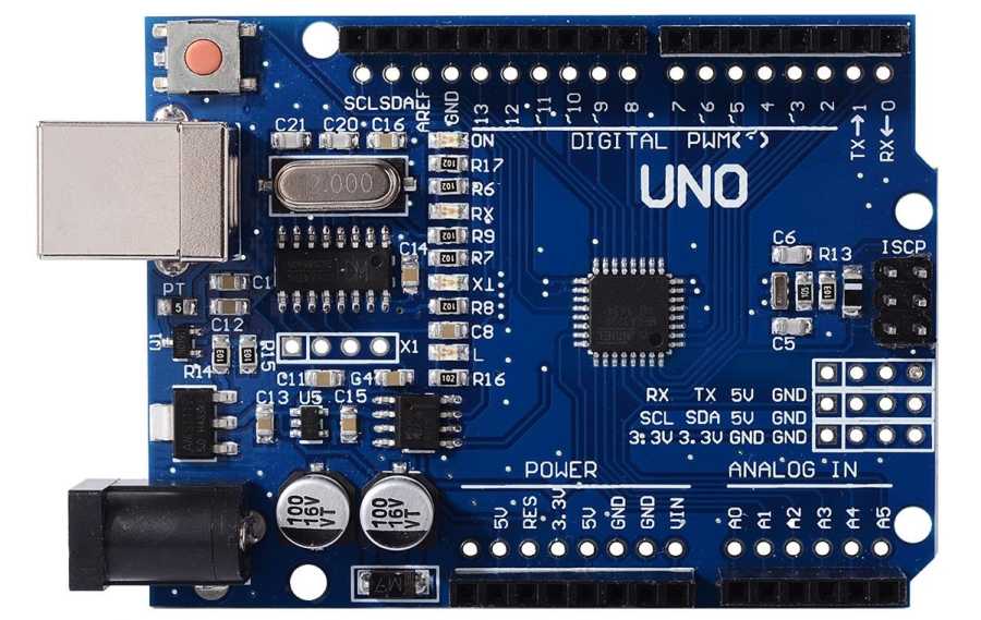
Pinout of the Module:
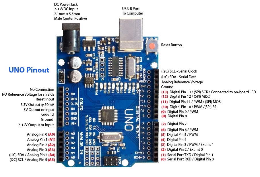
| Pin | Description |
|---|---|
| Serial Communication Pin | Connect to serial communication. 4 Pins (GND, VCC (3.3V or 5V controlled by slide switch), RX, TX) |
| Ground | Ground pins |
| V Pins (VCC) | Power the external sensors and modules. Voltage selectable (3.3V or 5V) via slide switch |
| Digital I/O | 14 digital input/output pins, labeled D0 to D13 (6 support PWM) |
| Digital port | Connect via female headers or pin headers (2.54mm pitch) |
| AREF | Analog reference for setting external reference voltage (0-5V) |
| SDA & SCL | I2C communication pins |
| ICSP Header | In-Circuit Serial Programming header with MOSI, MISO, SCK, RESET, VCC, and GND |
| Microcontroller | ATMEGA328P-AU (brain of the board) |
| D13 LED | Built-in LED on pin 13, ON when HIGH |
| TX LED | Flashes when board transmits data via serial |
| RX LED | Flashes when board receives data via serial |
| Power LED | On when board is powered |
| USB Connection | Power board or upload programs via USB cable |
| ATMEGA16U2-MU | USB to serial chip converting USB signals |
| Voltage regulator | Controls and stabilizes voltage to 5V for board components |
| DC Power Jack | External power input (7-12V) |
| RESET Header | Connect external reset button |
| 3.3V Output Pin | Provides 3.3V output |
| 5V Output Pin | Provides 5V output |
| Vin | External voltage input pin (7-12V) |
| Analog Pins | 6 analog inputs (A0 to A5), can also be used as digital pins (D14-D19) |
| IIC Communication Pin | 4 Pins (GND, VCC, SDA, SCL) |
| RESET Button | Reset the board to initial state |
Applications:
- Weighing Machines
- Traffic Light Count Down Timer
- Parking Lot Counter
- Embedded Systems
- Home Automation
- Industrial Automation
- Medical Instruments
- Emergency Light for Railways
Circuit:
No external circuit is needed for testing. You can rely on the built-in LED on pin 13.
Connecting with Arduino for the First Time:
- Open Arduino IDE: Download the Arduino IDE from the official software page. Also, download and install the CH340 driver following the provided instructions.
- Connect the Board: Use a USB data cable to connect the board to your computer. This will power the board and allow uploading of sketches.
- Select Board: In Arduino IDE, go to Tools > Board and select the appropriate Arduino UNO board.
- Select Port: Go to Tools > Port and select the port corresponding to your connected board.
- Upload a Sketch: Use an example sketch like Blink (File > Examples > 01.Basics > Blink), verify and upload it to your board. The onboard LED on pin 13 should blink.
Example Code:
void setup() {
  pinMode(13, OUTPUT);
}

void loop() {
  digitalWrite(13, HIGH);
  delay(1000);
  digitalWrite(13, LOW);
  delay(1000);
}
Technical Details:
- Input voltage: 7-12V
- Operating Voltage: 5 Volt
- Input Voltage Limits: 7 to 20 Volts
- DC Current per I/O Pin: 20 mA
- DC Current for 3.3V Pin: 50 mA
- Dimensions: Approx. 69mm x 53mm
Resources:
Comparisons:
This board is very similar to the Keyestudio UNO R3 Upgraded version. The SMD version uses the CH340 which requires a third-party driver. It has double pin headers for every pin, allowing connection using female or male pins. The Keyestudio version has a voltage switch to select 5V or 3.3V operation. Apart from the switch, extra pin headers, and the serial converter requiring a driver, the board is compatible with all Arduino UNO R3 code and shields.
Features:
- ATmega328 processor running at 16MHz
- CH340 Serial to USB converter
- 32KB Flash memory
- 14 Digital I/O
- 6 PWM shared with the digital I/O
- 6 Analog inputs that can also be used as digital I/O for a total of up to 20 digital I/O
- 1 Hardware serial port
- 5V Operation
Principle of Work:
Uno is Free hardware, which means its blueprints and specs are available for anybody to copy. Arduino provides the framework so any individual or business can design their own boards, unique yet functional when built on the same framework. Free software means the source code is available for anyone to use and alter.
To allow anyone to create apps for Arduino boards, Uno works with the Arduino IDE (Integrated Development Environment), which you can use to program and upload your code (sketch). This is done via an onboard Serial Converter with the help of an embedded bootloader, so no external programmer is needed.
The Uno uses libraries available online, giving you the ability to program many sensors and modules without needing to understand their inner workings.
Pinout of the Module:
| Pin | Description |
|---|---|
| Serial Communication Pin | Connect to serial communication. 4 Pins (GND, VCC (3.3V or 5V controlled by slide switch), RX, TX) |
| Ground | Ground pins |
| V Pins (VCC) | Power the external sensors and modules. Voltage selectable (3.3V or 5V) via slide switch |
| Digital I/O | 14 digital input/output pins, labeled D0 to D13 (6 support PWM) |
| Digital port | Connect via female headers or pin headers (2.54mm pitch) |
| AREF | Analog reference for setting external reference voltage (0-5V) |
| SDA & SCL | I2C communication pins |
| ICSP Header | In-Circuit Serial Programming header with MOSI, MISO, SCK, RESET, VCC, and GND |
| Microcontroller | ATMEGA328P-AU (brain of the board) |
| D13 LED | Built-in LED on pin 13, ON when HIGH |
| TX LED | Flashes when board transmits data via serial |
| RX LED | Flashes when board receives data via serial |
| Power LED | On when board is powered |
| USB Connection | Power board or upload programs via USB cable |
| ATMEGA16U2-MU | USB to serial chip converting USB signals |
| Voltage regulator | Controls and stabilizes voltage to 5V for board components |
| DC Power Jack | External power input (7-12V) |
| RESET Header | Connect external reset button |
| 3.3V Output Pin | Provides 3.3V output |
| 5V Output Pin | Provides 5V output |
| Vin | External voltage input pin (7-12V) |
| Analog Pins | 6 analog inputs (A0 to A5), can also be used as digital pins (D14-D19) |
| IIC Communication Pin | 4 Pins (GND, VCC, SDA, SCL) |
| RESET Button | Reset the board to initial state |
Applications:
- Weighing Machines
- Traffic Light Count Down Timer
- Parking Lot Counter
- Embedded Systems
- Home Automation
- Industrial Automation
- Medical Instruments
- Emergency Light for Railways
Circuit:
No external circuit is needed for testing. You can rely on the built-in LED on pin 13.
Connecting with Arduino for the First Time:
- Open Arduino IDE: Download the Arduino IDE from the official software page. Also, download and install the CH340 driver following the provided instructions.
- Connect the Board: Use a USB data cable to connect the board to your computer. This will power the board and allow uploading of sketches.
- Select Board: In Arduino IDE, go to Tools > Board and select the appropriate Arduino UNO board.
- Select Port: Go to Tools > Port and select the port corresponding to your connected board.
- Upload a Sketch: Use an example sketch like Blink (File > Examples > 01.Basics > Blink), verify and upload it to your board. The onboard LED on pin 13 should blink.
Example Code:
void setup() {
  pinMode(13, OUTPUT);
}

void loop() {
  digitalWrite(13, HIGH);
  delay(1000);
  digitalWrite(13, LOW);
  delay(1000);
}
Technical Details:
- Input voltage: 7-12V
- Operating Voltage: 5 Volt
- Input Voltage Limits: 7 to 20 Volts
- DC Current per I/O Pin: 20 mA
- DC Current for 3.3V Pin: 50 mA
- Dimensions: Approx. 69mm x 53mm
Resources:
Comparisons:
This board is very similar to the Keyestudio UNO R3 Upgraded version. The SMD version uses the CH340 which requires a third-party driver. It has double pin headers for every pin, allowing connection using female or male pins. The Keyestudio version has a voltage switch to select 5V or 3.3V operation. Apart from the switch, extra pin headers, and the serial converter requiring a driver, the board is compatible with all Arduino UNO R3 code and shields.