- All products
- Prototyping
- Components
- ICs
- Microcontrollers
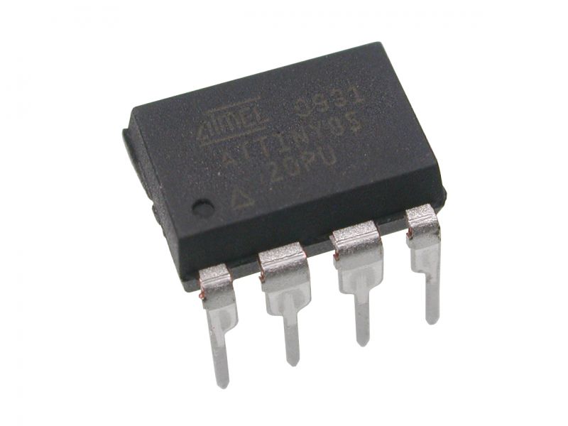
- Microcontrollers Atmel ATtiny85 20PU
- Microcontrollers
Features
- 8 KB flash memory for program storage
- 512 bytes EEPROM for non volatile data storage
- 512 bytes SRAM for runtime data
- 6 GPIO pins configurable as input or output
- PWM support for motor and LED control
- 4 analog input channels with 10 bit resolution
- SPI and I2C support through USI interface
- Maximum clock speed up to 20 MHz
- Operating voltage range from 2.7V to 5.5V
- Low power consumption suitable for battery devices
- DIP 8 pin package easy to mount on breadboard or PCB
Principle of Work
The microcontroller operates by executing instructions stored in its flash memory. It reads inputs from sensors or external signals through its pins, processes the data based on the program logic, and controls outputs such as LEDs, motors, or relays. The internal clock controls instruction timing, and configuration registers determine pin behavior and peripheral functions.
Pin Description Summary
- Pin 1: Reset or GPIO with ADC and interrupt functions
- Pin 2: GPIO or analog input or clock input
- Pin 3: GPIO with PWM and analog input capability
- Pin 4: Ground connection
- Pin 5: GPIO with PWM and I2C or SPI data support
- Pin 6: GPIO with PWM and SPI support
- Pin 7: GPIO with analog input and clock functions
- Pin 8: VCC power supply pin
Applications
- Battery powered sensor nodes
- Home automation and consumer electronics
- Small robotics projects
- Wearable devices
- Educational and learning projects
- Automotive control circuits
- Security and access control systems
Programming Overview
The ATtiny85 can be programmed using an Arduino Uno as an ISP programmer. After configuring the Arduino IDE with the appropriate board support, the microcontroller can be programmed using standard Arduino sketches. Once programmed, it operates independently according to the uploaded code.
Technical Details
- Architecture: 8 bit AVR
- Flash memory: 8 KB
- SRAM: 512 bytes
- EEPROM: 512 bytes
- Clock speed: up to 20 MHz
- Operating voltage: 2.7V to 5.5V
- ADC channels: 4
- PWM channels: 3
- Package type: DIP 8 pin
- Operating temperature range: industrial grade
Note: The PU suffix indicates an industrial temperature range. The number 20 refers to the maximum supported clock speed of 20 MHz.