IC Motor H-Bridge Driver 2Ch 0.6A 25V L293D
The L293D is a highly versatile H-bridge motor driver IC with two channels, capable of driving various motors including DC, stepper (unipolar and bipolar), and servos. Each channel can be used independently to drive solenoids or relays. It allows bidirectional control of DC motors and supports PWM signals for speed control. This IC is widely used in robotics, automation, and educational electronics projects.
Package Includes:
- 1 x L293D Motor Driver IC
Features:
- H-bridge circuit with two channels
- Capable of driving unipolar, bipolar stepper motors, DC motors, and servo motors
- Two half H-bridge circuits within it
- Can output PWM signal for motor speed control
- Each channel can drive solenoids or relays independently
- Drives two DC motors simultaneously
- Supports bidirectional motor control (forward/reverse)
- Handles up to 36V and 0.6A per channel (1.2A peak)
- Thermal shutdown protection
- Low saturation voltage drop
- Standard DIP-16 package for easy integration
Principle of Work:
The L293D contains two H-bridge circuits built with MOSFETs to control the direction and speed of DC or stepper motors. By toggling the input pins, the polarity across the motor terminals is changed, allowing directional control. Integrated diodes protect against back EMF from inductive loads. PWM signals can be used to control speed by modulating the enable pins.
Pinout:
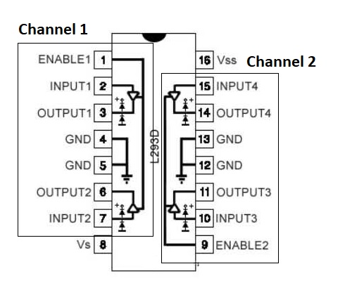
- VCC1 (Pin 16): Motor supply voltage (4.5V–36V)
- VCC2 (Pin 8): Logic voltage (5V–7V)
- Ground (Pins 4, 5, 12, 13): Ground connections
- Enable 1 (Pin 1): Enables first driver (IN1/IN2)
- Input 1 (Pin 2): Direction input 1
- Input 2 (Pin 7): Direction input 2
- Output 1 (Pin 3): Output to motor terminal 1
- Output 2 (Pin 6): Output to motor terminal 2
- Enable 2 (Pin 9): Enables second driver (IN3/IN4)
- Input 3 (Pin 10): Direction input 3
- Input 4 (Pin 15): Direction input 4
- Output 3 (Pin 11): Output to motor terminal 3
- Output 4 (Pin 14): Output to motor terminal 4
Applications:
- Robotics (DC motors, servos)
- Industrial automation (conveyor belts, actuators)
- Motor control systems (speed, torque, direction)
- Automotive systems (window motors, wipers)
- Home automation (motorized curtains, blinds)
- STEM and educational projects
Circuit Diagram:

- Red wire from battery: positive polarity
- Black wire from battery: ground
- Red/black wires to motor: set direction (clockwise/counter-clockwise)
- Green/yellow wires: direction control (IN1/IN2)
- Brown wire: speed control (EN)
Library:
No library required.
Example Arduino Code:
#define IN1 7
#define IN2 8
#define EN  9

void setup() {
  pinMode(IN1, OUTPUT);
  pinMode(IN2, OUTPUT);
  pinMode(EN, OUTPUT);
}

void setspeed(int val) {
  analogWrite(EN, val);
}

void setdir(bool dir) {
  digitalWrite(IN1, dir);
  digitalWrite(IN2, !dir);
}

void loop() {
  setdir(HIGH);
  for (int i = 0; i < 256; i++) {
    setspeed(i);
    delay(15);
  }
  for (int i = 255; i >= 0; i--) {
    setspeed(i);
    delay(15);
  }

  setdir(LOW);
  for (int i = 0; i < 256; i++) {
    setspeed(i);
    delay(15);
  }
  for (int i = 255; i >= 0; i--) {
    setspeed(i);
    delay(15);
  }
}
Code Explanation:
#define IN1 7,#define IN2 8, and#define EN 9define motor control pins.setup()initializes the motor control pins as outputs.setspeed(val)uses PWM on the EN pin to control motor speed.setdir(dir)sets direction by toggling IN1/IN2.loop()ramps the motor speed up and down in both directions.
Technical Details:
- Max motor supply voltage: 36V
- Max output current: 600mA per channel (1.2A peak)
- Built-in protection diodes
- Low quiescent current: 16mA
- Thermal shutdown protection
- Operating temperature: 0°C to 70°C
- PWM support for speed control
- Controls up to 2 DC motors or 1 stepper motor
- Available in 16-pin DIP/SMD package
Comparison with L298:
| Feature | L293D | L298 |
|---|---|---|
| Max Current | 600 mA/channel | 4 A/channel |
| Voltage Range | Up to 36V | Up to 48V |
| Channels | 2 | 2 (can be paralleled for higher current) |
| Heat Dissipation | Lower (no heatsink needed in most cases) | Higher (often requires heatsink) |
Resources:
Features:
- H-bridge circuit with two channels
- Capable of driving unipolar, bipolar stepper motors, DC motors, and servo motors
- Two half H-bridge circuits within it
- Can output PWM signal for motor speed control
- Each channel can drive solenoids or relays independently
- Drives two DC motors simultaneously
- Supports bidirectional motor control (forward/reverse)
- Handles up to 36V and 0.6A per channel (1.2A peak)
- Thermal shutdown protection
- Low saturation voltage drop
- Standard DIP-16 package for easy integration
Principle of Work:
The L293D contains two H-bridge circuits built with MOSFETs to control the direction and speed of DC or stepper motors. By toggling the input pins, the polarity across the motor terminals is changed, allowing directional control. Integrated diodes protect against back EMF from inductive loads. PWM signals can be used to control speed by modulating the enable pins.
Pinout:
- VCC1 (Pin 16): Motor supply voltage (4.5V–36V)
- VCC2 (Pin 8): Logic voltage (5V–7V)
- Ground (Pins 4, 5, 12, 13): Ground connections
- Enable 1 (Pin 1): Enables first driver (IN1/IN2)
- Input 1 (Pin 2): Direction input 1
- Input 2 (Pin 7): Direction input 2
- Output 1 (Pin 3): Output to motor terminal 1
- Output 2 (Pin 6): Output to motor terminal 2
- Enable 2 (Pin 9): Enables second driver (IN3/IN4)
- Input 3 (Pin 10): Direction input 3
- Input 4 (Pin 15): Direction input 4
- Output 3 (Pin 11): Output to motor terminal 3
- Output 4 (Pin 14): Output to motor terminal 4
Applications:
- Robotics (DC motors, servos)
- Industrial automation (conveyor belts, actuators)
- Motor control systems (speed, torque, direction)
- Automotive systems (window motors, wipers)
- Home automation (motorized curtains, blinds)
- STEM and educational projects
Circuit Diagram:
- Red wire from battery: positive polarity
- Black wire from battery: ground
- Red/black wires to motor: set direction (clockwise/counter-clockwise)
- Green/yellow wires: direction control (IN1/IN2)
- Brown wire: speed control (EN)
Library:
No library required.
Example Arduino Code:
#define IN1 7
#define IN2 8
#define EN  9

void setup() {
  pinMode(IN1, OUTPUT);
  pinMode(IN2, OUTPUT);
  pinMode(EN, OUTPUT);
}

void setspeed(int val) {
  analogWrite(EN, val);
}

void setdir(bool dir) {
  digitalWrite(IN1, dir);
  digitalWrite(IN2, !dir);
}

void loop() {
  setdir(HIGH);
  for (int i = 0; i < 256; i++) {
    setspeed(i);
    delay(15);
  }
  for (int i = 255; i >= 0; i--) {
    setspeed(i);
    delay(15);
  }

  setdir(LOW);
  for (int i = 0; i < 256; i++) {
    setspeed(i);
    delay(15);
  }
  for (int i = 255; i >= 0; i--) {
    setspeed(i);
    delay(15);
  }
}
Code Explanation:
#define IN1 7,#define IN2 8, and#define EN 9define motor control pins.setup()initializes the motor control pins as outputs.setspeed(val)uses PWM on the EN pin to control motor speed.setdir(dir)sets direction by toggling IN1/IN2.loop()ramps the motor speed up and down in both directions.
Technical Details:
- Max motor supply voltage: 36V
- Max output current: 600mA per channel (1.2A peak)
- Built-in protection diodes
- Low quiescent current: 16mA
- Thermal shutdown protection
- Operating temperature: 0°C to 70°C
- PWM support for speed control
- Controls up to 2 DC motors or 1 stepper motor
- Available in 16-pin DIP/SMD package
Comparison with L298:
| Feature | L293D | L298 |
|---|---|---|
| Max Current | 600 mA/channel | 4 A/channel |
| Voltage Range | Up to 36V | Up to 48V |
| Channels | 2 | 2 (can be paralleled for higher current) |
| Heat Dissipation | Lower (no heatsink needed in most cases) | Higher (often requires heatsink) |