Features:
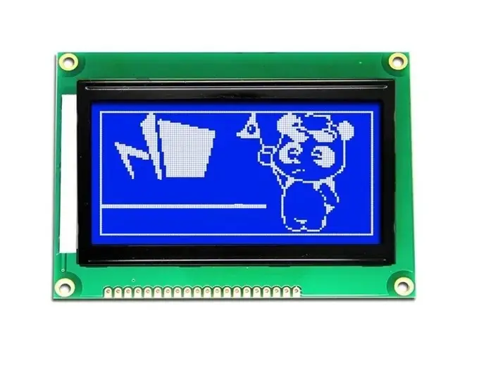
- Resolution: 128x64 pixels for rich graphical display
- Interfaces: Supports 8-bit parallel or 4-wire SPI communication
- Modes: Text, graphics, and mixed display modes
- Backlight: Adjustable for visibility under various lighting conditions
- Power Efficient: Low power consumption suitable for battery-powered devices
- High Contrast: Clear and easy-to-read output
- Custom Characters: Built-in character generator for custom symbols
- Temperature Range: Operates in wide environmental conditions
Principle of Work:
The display receives commands and data via SPI or parallel interface from a microcontroller. It supports multiple display modes, and its character generator allows creation of custom graphics by defining pixel patterns (up to 256 custom characters). These are stored in memory and rendered on screen through the ST7920 controller.
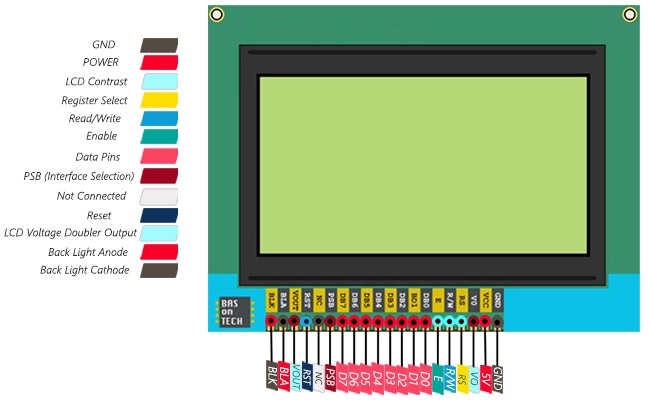
Pinout of the Module:
| Pin | Name | Description |
|---|---|---|
| 1 | VSS | Ground |
| 2 | VDD | Power supply (5V or 3.3V) |
| 3 | VO | Contrast adjustment via potentiometer |
| 4 | RS | Register Select (0 = instruction, 1 = data) |
| 5 | R/W | Read/Write signal (0 = write, 1 = read) |
| 6 | E | Enable signal |
| 7 | PSB | Mode select: 0 = parallel, 1 = SPI |
| 8–15 | DB0–DB7 | Data bus bits (used in parallel mode) |
| 16 | CS1 | Chip select (SPI/Parallel) |
| 17 | CS2 | Optional chip select (parallel or NC) |
| 18 | RST | Reset (active low) |
| 19 | LED-A | Backlight Anode (connect with resistor to 5V) |
| 20 | LED-K | Backlight Cathode (GND) |
Applications:
- Consumer electronics (TVs, monitors, tablets)
- Industrial controls (PLC panels, HMIs)
- Medical devices (monitors, diagnostics)
- Automotive (dashboards, infotainment)
- Gaming (handhelds, arcade machines)
- Instrumentation (oscilloscopes, analyzers)
- Advertising (digital signage, kiosks)
- Military and aerospace (navigation, cockpit displays)
Circuit Diagram:
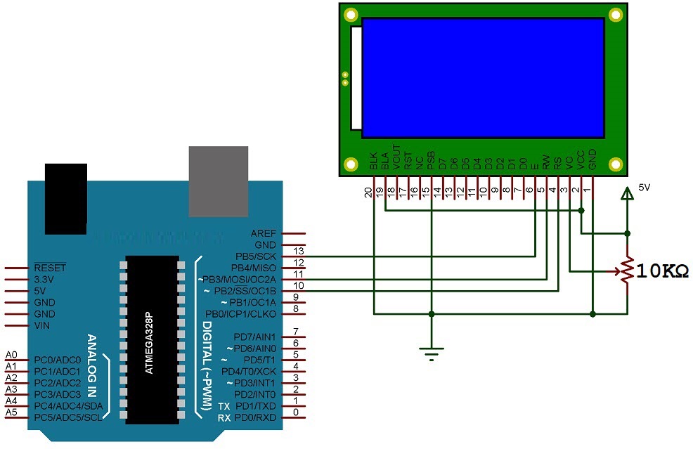
- RS → Arduino pin 10
- RW → Arduino pin 11
- E → Arduino pin 13
- PSB → GND (for SPI mode)
- VCC/GND → Power supply
- VO → Middle pin of 10K potentiometer
- LED-A → 5V (with resistor)
- LED-K → GND
Library:
- Open Arduino IDE → Sketch → Include Library → Manage Libraries
- Search for “U8g2”
- Select “U8g2 by Oliver” → Click Install
- Once installed, use
#include <U8g2lib.h>in your code
Example Code:
#include <Arduino.h>
#include <U8g2lib.h>

#ifdef U8X8_HAVE_HW_SPI
#include <SPI.h>
#endif
#ifdef U8X8_HAVE_HW_I2C
#include <Wire.h>
#endif

// Example Bitmap for 128x64 screen
static const unsigned char myBitmap [] PROGMEM = {
  0xf8, 0xff, 0xff, 0xff, /* ... truncated for brevity ... */ 0x00
};

// You would initialize your U8g2 display here depending on your wiring
// Example: U8G2_ST7920_128X64_F_HW_SPI u8g2(U8G2_R0, /* CS=*/ 10, /* reset=*/ 8);
Replace the U8g2 constructor line with the correct one for your hardware and wiring.
Features:
- Resolution: 128x64 pixels for rich graphical display
- Interfaces: Supports 8-bit parallel or 4-wire SPI communication
- Modes: Text, graphics, and mixed display modes
- Backlight: Adjustable for visibility under various lighting conditions
- Power Efficient: Low power consumption suitable for battery-powered devices
- High Contrast: Clear and easy-to-read output
- Custom Characters: Built-in character generator for custom symbols
- Temperature Range: Operates in wide environmental conditions
Principle of Work:
The display receives commands and data via SPI or parallel interface from a microcontroller. It supports multiple display modes, and its character generator allows creation of custom graphics by defining pixel patterns (up to 256 custom characters). These are stored in memory and rendered on screen through the ST7920 controller.
Pinout of the Module:
| Pin | Name | Description |
|---|---|---|
| 1 | VSS | Ground |
| 2 | VDD | Power supply (5V or 3.3V) |
| 3 | VO | Contrast adjustment via potentiometer |
| 4 | RS | Register Select (0 = instruction, 1 = data) |
| 5 | R/W | Read/Write signal (0 = write, 1 = read) |
| 6 | E | Enable signal |
| 7 | PSB | Mode select: 0 = parallel, 1 = SPI |
| 8–15 | DB0–DB7 | Data bus bits (used in parallel mode) |
| 16 | CS1 | Chip select (SPI/Parallel) |
| 17 | CS2 | Optional chip select (parallel or NC) |
| 18 | RST | Reset (active low) |
| 19 | LED-A | Backlight Anode (connect with resistor to 5V) |
| 20 | LED-K | Backlight Cathode (GND) |
Applications:
- Consumer electronics (TVs, monitors, tablets)
- Industrial controls (PLC panels, HMIs)
- Medical devices (monitors, diagnostics)
- Automotive (dashboards, infotainment)
- Gaming (handhelds, arcade machines)
- Instrumentation (oscilloscopes, analyzers)
- Advertising (digital signage, kiosks)
- Military and aerospace (navigation, cockpit displays)
Circuit Diagram:
- RS → Arduino pin 10
- RW → Arduino pin 11
- E → Arduino pin 13
- PSB → GND (for SPI mode)
- VCC/GND → Power supply
- VO → Middle pin of 10K potentiometer
- LED-A → 5V (with resistor)
- LED-K → GND
Library:
- Open Arduino IDE → Sketch → Include Library → Manage Libraries
- Search for “U8g2”
- Select “U8g2 by Oliver” → Click Install
- Once installed, use
#include <U8g2lib.h>in your code
Example Code:
#include <Arduino.h>
#include <U8g2lib.h>

#ifdef U8X8_HAVE_HW_SPI
#include <SPI.h>
#endif
#ifdef U8X8_HAVE_HW_I2C
#include <Wire.h>
#endif

// Example Bitmap for 128x64 screen
static const unsigned char myBitmap [] PROGMEM = {
  0xf8, 0xff, 0xff, 0xff, /* ... truncated for brevity ... */ 0x00
};

// You would initialize your U8g2 display here depending on your wiring
// Example: U8G2_ST7920_128X64_F_HW_SPI u8g2(U8G2_R0, /* CS=*/ 10, /* reset=*/ 8);
Replace the U8g2 constructor line with the correct one for your hardware and wiring.