The ESP32 NodeMcu (Type-C) is a versatile, low-cost WiFi and Bluetooth-enabled development board based on the ESP32 microcontroller. It features dual-core processing, 4MB flash memory, and a wide range of connectivity options, including WiFi, Bluetooth, and several serial communication protocols. The board can be programmed using the Arduino IDE or with other programming languages like MicroPython or Lua. It's popular for projects that require wireless connectivity and low power consumption, such as IoT devices, home automation, and robotics.
Package Includes:
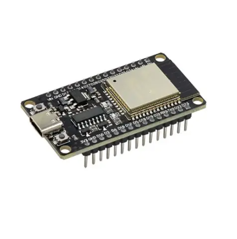
- 1 × ESP32 NodeMcu Board (USB Type-C connector, CH340 USB-to-serial)