Digispark ATtiny85 Black
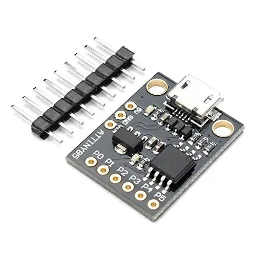
The Digispark Black is a compact and cost-effective microcontroller development board based on the ATtiny85. It offers Arduino-like functionality in a smaller form factor (23 x 17.5mm) and includes a built-in USB bootloader for easy programming.
Package Includes:
- 1 x Digispark 85 Black Development Board
Features:
- Compact Design: Small form factor ideal for space-constrained projects.
- Microcontroller: Based on the AVR ATtiny85 8-bit microcontroller.
- Digital I/O: 6 digital I/O pins, with 4 capable of PWM output.
- Analog Inputs: 4 analog input pins for sensor integration.
- Memory: 512 bytes SRAM, 512 bytes EEPROM, 6KB user flash memory (from 8KB total, 2KB used by bootloader).
- Clock Speed: 16.5 MHz for fast performance.
- I2C and SPI Support: Compatible with I2C and SPI protocols.
- Status Indicators: Power and status LEDs.
- Power Supply: 7–12V input with onboard 5V regulation.
- Regulated 5V Output: Onboard voltage regulator ensures stable 5V for peripherals.
Description:
The Digispark Black brings ATtiny85 functionality in a USB-ready form. It can be programmed via Arduino IDE using C/C++, despite the ATtiny85 lacking a native USB controller. Thanks to the V-USB library, the board emulates USB 1.1, enabling the creation of devices like HID keyboards or virtual serial ports. The board is ideal for applications needing minimal I/O but solid microcontroller capabilities.
Principle of Work:
- USB Bootloader: Enables direct USB connection without an external programmer.
- Code Uploading: The bootloader uses a virtual serial port for programming via Arduino IDE.
- Execution: Code runs from flash memory after a 5-second bootloader delay.
Pinout Diagram:
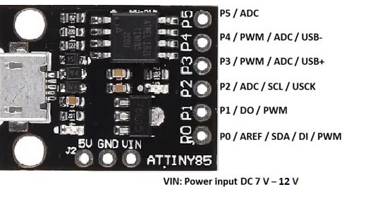
Pinout Functions:
| Interface | Pins |
|---|---|
| GPIO | P0, P1, P2, P3, P4, P5 (6 GPIO) |
| SPI | MOSI (P0), MISO (P1), SCK (P2) |
| PWM | P0, P1, P3, P4 (4 PWM) |
| ADC | A1, A3, A4, A5 (4 ADC) |
| I2C | SDA (P0), SCL (P2) |
Pin Descriptions:
- Digital I/O: 6 pins, 4 with PWM.
- Analog Inputs: 4 channels for analog sensors.
- AREF: Reference voltage for analog input range configuration.
- SDA/SCL: Used for I2C communication.
- USB: Built-in USB via V-USB software implementation.
- Onboard LED: Connected to pin 1 for debugging or status indication.
- Voltage Regulator: Converts 7–12V input to 5V regulated output.
- 5V Pin: Provides regulated 5V output for external components.
- Vin: External power input (7–12V DC).
- Power LED: Indicates board is powered on.
Applications:
- DIY Electronics and Prototyping
- Home Automation Systems
- Internet of Things (IoT)
- Wearable Devices
- Robotics and Automation
- Environmental Monitoring
- Data Logging Projects
- Educational Microcontroller Training
Getting Started:
- Download and install the Arduino IDE.
- Plug in the Digispark via USB.
- Add URL to Additional Boards Manager:
http://digistump.com/package_digistump_index.json - Install Digistump AVR boards via Boards Manager.
- Install Windows drivers (use
DPinst64.exeorDPinst.exe). - Select board: Digispark (Default - 16.5 MHz)
- Upload code: Press upload, then plug in board when prompted.
Sample Code:
void setup() {
  pinMode(0, OUTPUT); // Set pin 0 as output
}

void loop() {
  digitalWrite(0, HIGH); // Turn on LED
  delay(1000);           // Wait 1 second
  digitalWrite(0, LOW);  // Turn off LED
  delay(1000);           // Wait 1 second
}
Technical Specifications:
- Microcontroller: ATtiny85
- Clock Speed: 16.5 MHz
- Operating Voltage: 5V
- Input Voltage (Recommended): 7–12V
- Digital I/O Pins: 6
- Rated Current per Pin: 20mA
- DC Current for 5V Pin: 500mA
- SRAM: 512 bytes
- EEPROM: 512 bytes
- Flash Memory: 8KB (6KB usable)
- Power Consumption: 300μA (active @1.8V), 0.1μA (power down)
- Operating Temp: -40°C to 105°C
- Board Size: 23 x 17.5mm
Resources:
Features:
- Compact Design: Small form factor ideal for space-constrained projects.
- Microcontroller: Based on the AVR ATtiny85 8-bit microcontroller.
- Digital I/O: 6 digital I/O pins, with 4 capable of PWM output.
- Analog Inputs: 4 analog input pins for sensor integration.
- Memory: 512 bytes SRAM, 512 bytes EEPROM, 6KB user flash memory (from 8KB total, 2KB used by bootloader).
- Clock Speed: 16.5 MHz for fast performance.
- I2C and SPI Support: Compatible with I2C and SPI protocols.
- Status Indicators: Power and status LEDs.
- Power Supply: 7–12V input with onboard 5V regulation.
- Regulated 5V Output: Onboard voltage regulator ensures stable 5V for peripherals.
Description:
The Digispark Black brings ATtiny85 functionality in a USB-ready form. It can be programmed via Arduino IDE using C/C++, despite the ATtiny85 lacking a native USB controller. Thanks to the V-USB library, the board emulates USB 1.1, enabling the creation of devices like HID keyboards or virtual serial ports. The board is ideal for applications needing minimal I/O but solid microcontroller capabilities.
Principle of Work:
- USB Bootloader: Enables direct USB connection without an external programmer.
- Code Uploading: The bootloader uses a virtual serial port for programming via Arduino IDE.
- Execution: Code runs from flash memory after a 5-second bootloader delay.
Pinout Diagram:
Pinout Functions:
| Interface | Pins |
|---|---|
| GPIO | P0, P1, P2, P3, P4, P5 (6 GPIO) |
| SPI | MOSI (P0), MISO (P1), SCK (P2) |
| PWM | P0, P1, P3, P4 (4 PWM) |
| ADC | A1, A3, A4, A5 (4 ADC) |
| I2C | SDA (P0), SCL (P2) |
Pin Descriptions:
- Digital I/O: 6 pins, 4 with PWM.
- Analog Inputs: 4 channels for analog sensors.
- AREF: Reference voltage for analog input range configuration.
- SDA/SCL: Used for I2C communication.
- USB: Built-in USB via V-USB software implementation.
- Onboard LED: Connected to pin 1 for debugging or status indication.
- Voltage Regulator: Converts 7–12V input to 5V regulated output.
- 5V Pin: Provides regulated 5V output for external components.
- Vin: External power input (7–12V DC).
- Power LED: Indicates board is powered on.
Applications:
- DIY Electronics and Prototyping
- Home Automation Systems
- Internet of Things (IoT)
- Wearable Devices
- Robotics and Automation
- Environmental Monitoring
- Data Logging Projects
- Educational Microcontroller Training
Getting Started:
- Download and install the Arduino IDE.
- Plug in the Digispark via USB.
- Add URL to Additional Boards Manager:
http://digistump.com/package_digistump_index.json - Install Digistump AVR boards via Boards Manager.
- Install Windows drivers (use
DPinst64.exeorDPinst.exe). - Select board: Digispark (Default - 16.5 MHz)
- Upload code: Press upload, then plug in board when prompted.
Sample Code:
void setup() {
  pinMode(0, OUTPUT); // Set pin 0 as output
}

void loop() {
  digitalWrite(0, HIGH); // Turn on LED
  delay(1000);           // Wait 1 second
  digitalWrite(0, LOW);  // Turn off LED
  delay(1000);           // Wait 1 second
}
Technical Specifications:
- Microcontroller: ATtiny85
- Clock Speed: 16.5 MHz
- Operating Voltage: 5V
- Input Voltage (Recommended): 7–12V
- Digital I/O Pins: 6
- Rated Current per Pin: 20mA
- DC Current for 5V Pin: 500mA
- SRAM: 512 bytes
- EEPROM: 512 bytes
- Flash Memory: 8KB (6KB usable)
- Power Consumption: 300μA (active @1.8V), 0.1μA (power down)
- Operating Temp: -40°C to 105°C
- Board Size: 23 x 17.5mm