Skip to Content

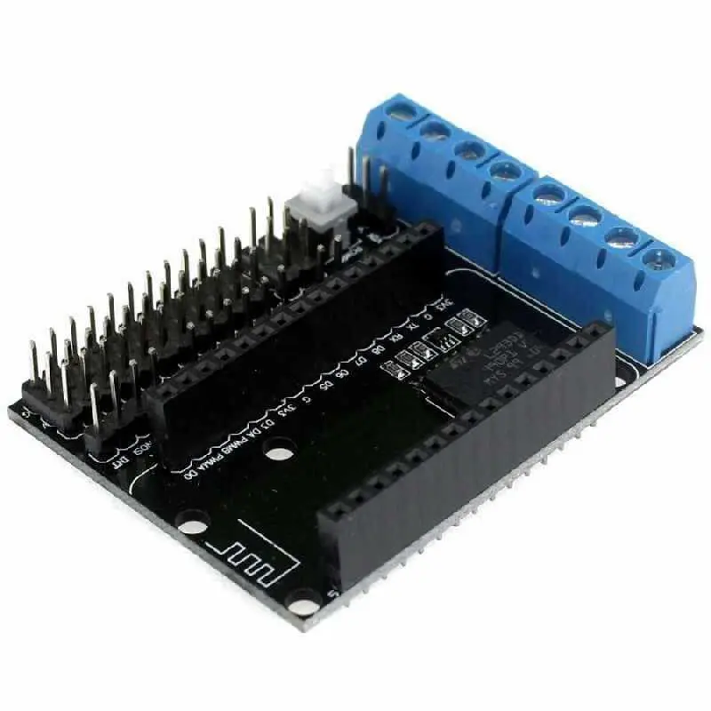
Motor Driver Shield Board L293D For NodeMCU V2

The Motor Shield is built around the L293D quadruple high-current half-H driver, a reliable IC for driving motors. Designed for use with NodeMCU, this shield simplifies motor control by utilizing GPIO ports. It supports driving up to two motors, offering robust performance and easy integration.

Package Includes:

  • 1 x Motor Shield for NodeMCU
  • Note: NodeMCU V2 board is not included.

19.95 AED 19.95 AED Tax Included
19.95 AED Tax Included

Not Available For Sale

This combination does not exist.

ESP8266 NodeMCU Shield

Terms and Conditions
30-day money-back guarantee
Shipping: 2-3 Business Days


Features:

  • Dual Motor Support: Control two motors simultaneously with separate speed and direction settings.
  • Independent Power Supplies: Motor power supply (VM) and control power (VIN) can operate separately or be merged using the short-circuit submodule.
  • High-Performance Driver: Powered by a dual high-power H-bridge driver (L293D), suitable for demanding applications.
  • Versatile Power Range:
    • Motor power supply: 4.5V–36V
    • Control power supply: 4.5V–9V
  • Compact and Reliable: Withstands high temperatures (up to 125°C) and offers short-circuit protection for safe operation.

Specifications:

  • Motor Power Supply (VM): 4.5V–36V
  • Control Power Supply (VIN): 4.5V–9V (10V MAX)
  • Logic Operating Current (Iss): ≤60mA (Vi = L), ≤22mA (Vi = H)
  • Drive Current (Io): ≤1.2A
  • Maximum Power Dissipation: 4W (T = 90°C)
  • Input Signal Level:
    • High: 2.3V ≤ VIH ≤ VIN
    • Low: -0.3V ≤ VIL ≤ 1.5V
  • Working Temperature: -25°C to 125°C
  • Drive Type: Dual high-power H-bridge driver

Pinout:

Motor Shield Pin NodeMCU Pin GPIO Purpose
PWMA (Motor A) D1 GPIO 5 Speed Control
DIRA (Motor A) D3 GPIO 0 Direction Control
PWMB (Motor B) D2 GPIO 4 Speed Control
DIRB (Motor B) D4 GPIO 2 Direction Control

Notice:

  1. Power Configuration:
    • Motor and control power can operate independently.
    • Short the VIN and VM pins for combined power input (4.5V–9V).
  2. Module Alignment:
    • When connecting the ESP-12E module, ensure the antenna direction matches the expansion board orientation.
  3. Integrated Short Circuit Module:
    • Enables simultaneous control of both the board and motor for streamlined operation.