Features:
- Power-On LED: Indicates when the module is powered (LED1)
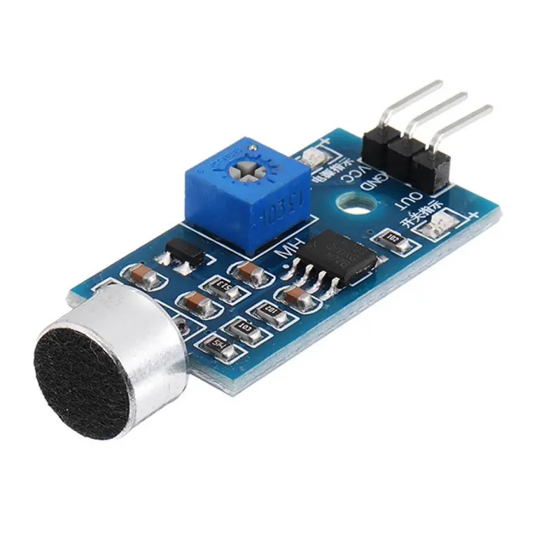
- Electret Condenser Microphone (ECM): Captures sound signals from the environment
- Output Status LED: (LED2) Illuminates when sound exceeds the threshold
- Built-in Potentiometer: Allows adjustment of the digital output (DO) sensitivity threshold
- Mounting Hole: Includes 3mm mounting hole for easy installation
Principle of Operation:
Sound waves cause the microphone diaphragm to vibrate, changing the capacitance and generating a voltage. This voltage is processed by the onboard comparator (LM393), which outputs a digital signal based on the preset threshold.
Pinout of the Module:
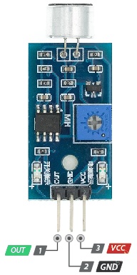
- VCC: Power supply (3.3V to 5V)
- GND: Ground
- OUT: Digital Output – LOW when sound is detected, HIGH otherwise
Applications:
- Clap-activated switch projects
- Sound-triggered LED or relay systems
- Animal noise monitoring
- Security systems
Circuit Diagram:
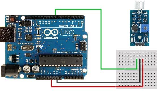
Connect the module’s VCC and GND to 5V and GND on the Arduino. Connect OUT to digital pin 7.
Arduino Code Example:
#define sensorPin 7
unsigned long lastEvent = 0;

void setup() {
  pinMode(sensorPin, INPUT);
  Serial.begin(9600);
}

void loop() {
  int sensorData = digitalRead(sensorPin);

  if (sensorData == LOW) {
    if (millis() - lastEvent > 25) {
      Serial.println("Clap detected!");
    }
    lastEvent = millis();
  }
}
This code outputs "Clap detected!" to the Serial Monitor when a sound is detected.
Technical Details:
- Mounting Hole Diameter: 3mm
- Comparator IC: LM393
- Power Supply: +5V
- Dimensions: 35mm x 15mm x 14mm (L x W x H)
- Color: Blue
Resources:
Comparison:
This module is perfect for binary (digital) sound detection without needing a microcontroller—just connect it directly to a relay. However, for analog sound level monitoring, consider a different sensor with analog output capabilities.
Features:
- Power-On LED: Indicates when the module is powered (LED1)
- Electret Condenser Microphone (ECM): Captures sound signals from the environment
- Output Status LED: (LED2) Illuminates when sound exceeds the threshold
- Built-in Potentiometer: Allows adjustment of the digital output (DO) sensitivity threshold
- Mounting Hole: Includes 3mm mounting hole for easy installation
Principle of Operation:
Sound waves cause the microphone diaphragm to vibrate, changing the capacitance and generating a voltage. This voltage is processed by the onboard comparator (LM393), which outputs a digital signal based on the preset threshold.
Pinout of the Module:
- VCC: Power supply (3.3V to 5V)
- GND: Ground
- OUT: Digital Output – LOW when sound is detected, HIGH otherwise
Applications:
- Clap-activated switch projects
- Sound-triggered LED or relay systems
- Animal noise monitoring
- Security systems
Circuit Diagram:
Connect the module’s VCC and GND to 5V and GND on the Arduino. Connect OUT to digital pin 7.
Arduino Code Example:
#define sensorPin 7
unsigned long lastEvent = 0;

void setup() {
  pinMode(sensorPin, INPUT);
  Serial.begin(9600);
}

void loop() {
  int sensorData = digitalRead(sensorPin);

  if (sensorData == LOW) {
    if (millis() - lastEvent > 25) {
      Serial.println("Clap detected!");
    }
    lastEvent = millis();
  }
}
This code outputs "Clap detected!" to the Serial Monitor when a sound is detected.
Technical Details:
- Mounting Hole Diameter: 3mm
- Comparator IC: LM393
- Power Supply: +5V
- Dimensions: 35mm x 15mm x 14mm (L x W x H)
- Color: Blue
Resources:
Comparison:
This module is perfect for binary (digital) sound detection without needing a microcontroller—just connect it directly to a relay. However, for analog sound level monitoring, consider a different sensor with analog output capabilities.