Features:
- Dual Power Supply Compatibility: This module is compatible with both 3.3v and 5v power supplies, offering flexibility in your project's power requirements.
- Integrated MAX9812 Signal Amplifier IC: It features a built-in MAX9812 signal amplifier IC, known for its professional-grade audio amplification capabilities.
- Fixed 20dB Gain: The module provides a fixed gain of 20dB, ensuring consistent and clear audio amplification for your applications.
- Wide Bandwidth: With a bandwidth of 500kHz, it can capture a wide range of audio frequencies, making it suitable for various sound-related projects.
- Low Noise and Low Signal Distortion: The MAX9812 Microphone Amplifier Module boasts minimal noise and low signal distortion, with a THD (Total Harmonic Distortion) of only 0.015%. This ensures high-quality audio output.
- Breadboard Friendly: Its compact design and standardized pin layout make it easy to integrate into your breadboard projects, simplifying the prototyping process.
- Small Form Factor: The module's small size makes it suitable for applications where space is limited, allowing for more versatile project designs.
- Mounting Holes: For added convenience in installation, the module includes mounting holes, making it easy to secure in your project enclosure or setup.
Principle of Work:
The MAX9812 Microphone Amplifier Sound MIC Voice Module operates with the Maxim MAX9812 microphone amplifier, which is a low-power fixed-gain amplifier available in single- or dual-input configurations. Its primary function is to amplify the audio signal from an electret condenser microphone (ECM) and interface it with a microcontroller unit (MCU). in the following you can read about how the module works internally and interacts with an MCU:
-
Microphone Amplification:
- The module features a built-in Maxim MAX9812 microphone amplifier, which offers a fixed gain of 10V/V (equivalent to 20dB). This means it amplifies the input audio signal by a factor of 20.
-
Bandwidth and Low Noise:
- The MAX9812 amplifier has a bandwidth of 400kHz with a -3dB cutoff point. This wide bandwidth allows it to capture a broad range of audio frequencies.
- It is designed to maintain low noise levels, ensuring that the amplified audio signal remains clean and free from interference.
-
Input Configuration:
- The module can come in either single-input (MAX9812) or dual-input (MAX9813L/MAX9813H) configurations.
- In the dual-input version, a 2:1 multiplexer allows you to select between two different audio input channels. The selection is made using the IN1/IN2 pin, driven by logic signals.
- Switching between input channels has a 10µs switching time, ensuring smooth transitions.
-
Microphone Bias Voltage (BIAS):
- The MAX9812 provides a regulated BIAS voltage, typically 2.3V for the MAX9812L/MAX9813L and 4V for the MAX9812H/MAX9813H.
- This BIAS voltage is designed for biasing electret condenser microphone (ECM) cartridges, which require a stable voltage source.
-
Output Stage:
- The module's output (OUT) is rail-to-rail, typically swinging to within 100mV of the supply rails when driving a load of 10kΩ.
- The DC bias point of the output is set to 1.5V for the MAX9812L/MAX9813L and 2.5V for the MAX9812H/MAX9813H.
-
Shutdown Mode (SHDN):
- The SHDN pin controls whether the MAX9812 is active or in shutdown mode.
- Driving SHDN low places the module in a low-power (100nA) shutdown mode, where the OUT pin goes into a high-impedance state, and the BIAS pin is pulled down.
- Driving SHDN high enables the module for normal operation.
-
Driving Capacitive Loads:
- The MAX9812 output can handle capacitive loads of up to 50pF without causing sustained oscillations or instability.
-
Thermal Shutdown:
- The module includes a thermal shutdown feature that protects it from overheating.
- When the die temperature reaches +140°C, the OUT and BIAS pins are shut down and go into a high-impedance state to prevent damage.
- Normal operation resumes once the die temperature falls below +120°C.
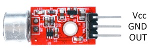
Pinout of the Module:
-
VCC (Power Supply):
- Voltage Range: 3-5V DC
- This is the power supply pin for the module. It accepts a voltage range of 3 to 5 volts DC. Make sure to connect it to a suitable power source within this range to power the module.
-
GND (Ground):
- The GND pin is the ground connection, providing the reference point for the module's electrical circuit. Connect this pin to the ground (0V) of your power supply or MCU to establish a common ground reference.
-
OUT (Output Signal):
- The OUT pin is where the amplified audio signal is output from the module. Connect this pin to the analog input of your microcontroller or other audio processing equipment to access the amplified audio signal for further processing or recording.
Applications:
- Voice Recording: Use the module to capture and amplify voice signals for recording applications. It's suitable for building voice recorders, dictation devices, or voice-activated systems.
- Sound Detection: Create sound-activated systems or devices that respond to specific audio cues. For example, you can design clap-activated switches, sound-activated alarms, or voice-controlled appliances.
- Voice Communication: Incorporate the module into intercom systems or communication devices to enhance the sensitivity and clarity of voice communication.
- Audio Sampling: It can be used in audio sampling applications, such as musical instrument pickups or audio analyzers, to capture and process sound data.
- Environmental Monitoring: Monitor and analyze ambient sounds in various environments. This can be useful for noise pollution monitoring, wildlife audio recording, or acoustic studies.
- Voice Assistants: Integrate the module into DIY voice assistant projects, allowing you to create your own voice-controlled smart devices.
- Home Automation: Implement the module in home automation projects, enabling voice commands to control lights, appliances, or other smart home devices.
- Security Systems: Enhance security systems with audio detection capabilities. The module can be used in intruder detection systems that trigger alarms based on unusual sounds.
- Pet Monitoring: Monitor and interact with pets remotely by capturing their sounds and responding accordingly. This is useful for pet owners who want to check on their pets when away from home.
- Educational Projects: Use the module for educational purposes in schools or electronics workshops to teach students about audio amplification and signal processing.
- DIY Audio Projects: Incorporate the module into DIY audio amplifier projects, preamplifiers, or audio effects units to enhance sound quality and versatility.
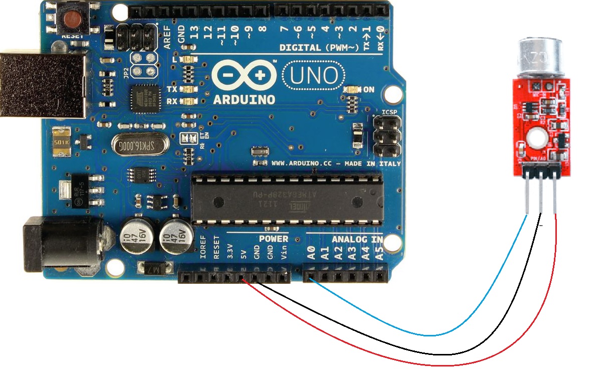
Circuit:
The electrical setup is straightforward. To power the module, you connect the GND and 5V pins of the module to the corresponding GND and 5V pins on the Arduino. Then, for data transmission, you connect the analog output of the sensor to one of the Arduino's analog input pins.
The pin mapping for MAX-9812 and Arduino:
- MAX-9812 -> Arduino
- VCC (5V) -> 5V
- GND -> GND
- OUT -> A0
Library:
This Module doesn't need a library to work.
Code:
this code is a basic example of how to interface with the MAX9812 module and perform sound amplitude measurements using an Arduino, continuously measures the sound amplitude from the microphone module, converts it to voltage, and displays the voltage value on the Arduino's serial monitor:
const int sensorPIN = A0;
const int sampleWindow = 50; // Window width in milliseconds (50 ms = 20 Hz)

void setup() {
  Serial.begin(9600); // Initialize serial communication
}

void loop() {
  unsigned long startMillis = millis();
  unsigned int signalMax = 0;
  unsigned int signalMin = 1024;

  // Collect data during the sample window
  unsigned int sample;
  while (millis() - startMillis < sampleWindow) {
    sample = analogRead(sensorPIN);

    if (sample < 1024) {
      if (sample > signalMax) {
        signalMax = sample; // Update maximum
      } else if (sample < signalMin) {
        signalMin = sample; // Update minimum
      }
    }
  }

  unsigned int peakToPeak = signalMax - signalMin; // Sound amplitude
  double volts = (peakToPeak * 5.0) / 1024; // Convert to voltage

  Serial.println(volts); // Print the voltage value to the serial monitor
}
-
Initialization:
- It begins by defining constants and variables.
sensorPINspecifies the analog pin (A0) where the module's output is connected, andsampleWindowsets the duration of the data collection window in milliseconds (50 ms, equivalent to a sampling rate of 20 Hz).
- It begins by defining constants and variables.
-
Setup:
- In the
setup()function, it initializes serial communication with a baud rate of 9600, which allows you to monitor the output on the Arduino's serial monitor.
- In the
-
Loop:
- The
loop()function is where the main action happens, and it runs repeatedly. - It starts by recording the current time using
millis()and initializing variables for the maximum and minimum signal values (signalMaxandsignalMin).
- The
-
Data Collection:
- Inside a
whileloop, the code continuously reads analog values fromsensorPINand checks if the value is within the valid range (less than 1024, which is the maximum analog reading value). - It updates
signalMaxwith the highest value encountered andsignalMinwith the lowest value encountered during the data collection window.
- Inside a
-
Amplitude Calculation:
- After the data collection window, the code calculates the peak-to-peak amplitude of the sound signal by subtracting
signalMinfromsignalMax.
- After the data collection window, the code calculates the peak-to-peak amplitude of the sound signal by subtracting
-
Voltage Conversion:
- It then converts the peak-to-peak amplitude to voltage using the formula
(peakToPeak * 5.0) / 1024. This assumes a 5V reference voltage (common for Arduino analog pins).
- It then converts the peak-to-peak amplitude to voltage using the formula
-
Serial Output:
- Finally, it prints the calculated voltage value to the serial monitor using
Serial.println(volts).
- Finally, it prints the calculated voltage value to the serial monitor using
Technical Details:
- Gain at 20dB
-
Electret microphone: CZN-15E with a bandwidth of 20 - 16000 Hz
-
Sensitivity: -58±2dB (0dB=1V/pa,1KHz)
-
Signal amplification: 20 dB (voltage gain 10x)
-
Module supply voltages from 3.6 V to 5.9 V (recommended voltage 5.0 V )
-
Voltage regulator: 3.3V
- Board size: 15*9mm
Resources:
- IC Amplifier Max9812 Datasheet
- How to calculate decibels
Comparisons:
This is a comparison between the MAX9812 module and the Ky-037 and Ky-038 modules, highlighting their strengths and limitations, the MAX9812 is suitable for basic sound detection and amplification but lacks advanced audio capabilities. The Ky-037 and Ky-038 modules offer greater versatility and are better suited for sound-triggered projects, making them suitable choices for hobbyists and beginners:
MAX9812 Module:
-
Strengths:
- Suitable for simple sound detection tasks, such as clap detection or assessing overall loudness.
- Provides a fixed 20dB (10x) amplification of the input audio signal.
- Wide bandwidth of 400kHz, allowing it to capture a broad range of frequencies.
- Low-noise design for clean signal amplification.
-
Limitations:
- Not recommended for recording, processing, or playing back sound.
- May not provide sufficient output voltage levels for some applications.
- Primarily designed for basic sound detection and amplification.
-
Recommendation: Choose the MAX9812 module when you need to detect sounds, measure loudness, or trigger simple actions like turning on lights or alarms in response to sound events.
Ky-037 Module:
-
Strengths:
- More versatile than the MAX9812, suitable for basic sound detection and recording applications.
- Typically includes a microphone and a sound sensor.
- Can be used to trigger actions based on specific sound events.
- Suited for hobbyist and beginner-level audio projects.
-
Limitations:
- May not provide high-quality audio recording or playback capabilities.
- Limited amplification capabilities compared to dedicated audio amplifiers.
- Not designed for professional-grade sound processing.
-
Recommendation: Opt for the Ky-037 module when you need a more versatile sound sensor that can detect and respond to sound events and you're working on beginner or hobbyist-level audio projects.
Ky-038 Module:
-
Strengths:
- Similar to the Ky-037, it's versatile and suitable for sound detection tasks.
- Typically includes a microphone and a sound sensor.
- Can be used for basic sound-activated systems and projects.
- Beginner-friendly and easy to integrate into Arduino or similar platforms.
-
Limitations:
- Limited in terms of advanced audio recording, processing, or playback capabilities.
- Not designed for high-fidelity sound applications.
- Best suited for entry-level audio projects and sound-triggered actions.
-
Recommendation: Choose the Ky-038 module for simple sound detection and interaction projects, especially when you're working with microcontrollers like Arduino and require a straightforward sound sensor.
Features:
- Dual Power Supply Compatibility: This module is compatible with both 3.3v and 5v power supplies, offering flexibility in your project's power requirements.
- Integrated MAX9812 Signal Amplifier IC: It features a built-in MAX9812 signal amplifier IC, known for its professional-grade audio amplification capabilities.
- Fixed 20dB Gain: The module provides a fixed gain of 20dB, ensuring consistent and clear audio amplification for your applications.
- Wide Bandwidth: With a bandwidth of 500kHz, it can capture a wide range of audio frequencies, making it suitable for various sound-related projects.
- Low Noise and Low Signal Distortion: The MAX9812 Microphone Amplifier Module boasts minimal noise and low signal distortion, with a THD (Total Harmonic Distortion) of only 0.015%. This ensures high-quality audio output.
- Breadboard Friendly: Its compact design and standardized pin layout make it easy to integrate into your breadboard projects, simplifying the prototyping process.
- Small Form Factor: The module's small size makes it suitable for applications where space is limited, allowing for more versatile project designs.
- Mounting Holes: For added convenience in installation, the module includes mounting holes, making it easy to secure in your project enclosure or setup.
Principle of Work:
The MAX9812 Microphone Amplifier Sound MIC Voice Module operates with the Maxim MAX9812 microphone amplifier, which is a low-power fixed-gain amplifier available in single- or dual-input configurations. Its primary function is to amplify the audio signal from an electret condenser microphone (ECM) and interface it with a microcontroller unit (MCU). in the following you can read about how the module works internally and interacts with an MCU:
-
Microphone Amplification:
- The module features a built-in Maxim MAX9812 microphone amplifier, which offers a fixed gain of 10V/V (equivalent to 20dB). This means it amplifies the input audio signal by a factor of 20.
-
Bandwidth and Low Noise:
- The MAX9812 amplifier has a bandwidth of 400kHz with a -3dB cutoff point. This wide bandwidth allows it to capture a broad range of audio frequencies.
- It is designed to maintain low noise levels, ensuring that the amplified audio signal remains clean and free from interference.
-
Input Configuration:
- The module can come in either single-input (MAX9812) or dual-input (MAX9813L/MAX9813H) configurations.
- In the dual-input version, a 2:1 multiplexer allows you to select between two different audio input channels. The selection is made using the IN1/IN2 pin, driven by logic signals.
- Switching between input channels has a 10µs switching time, ensuring smooth transitions.
-
Microphone Bias Voltage (BIAS):
- The MAX9812 provides a regulated BIAS voltage, typically 2.3V for the MAX9812L/MAX9813L and 4V for the MAX9812H/MAX9813H.
- This BIAS voltage is designed for biasing electret condenser microphone (ECM) cartridges, which require a stable voltage source.
-
Output Stage:
- The module's output (OUT) is rail-to-rail, typically swinging to within 100mV of the supply rails when driving a load of 10kΩ.
- The DC bias point of the output is set to 1.5V for the MAX9812L/MAX9813L and 2.5V for the MAX9812H/MAX9813H.
-
Shutdown Mode (SHDN):
- The SHDN pin controls whether the MAX9812 is active or in shutdown mode.
- Driving SHDN low places the module in a low-power (100nA) shutdown mode, where the OUT pin goes into a high-impedance state, and the BIAS pin is pulled down.
- Driving SHDN high enables the module for normal operation.
-
Driving Capacitive Loads:
- The MAX9812 output can handle capacitive loads of up to 50pF without causing sustained oscillations or instability.
-
Thermal Shutdown:
- The module includes a thermal shutdown feature that protects it from overheating.
- When the die temperature reaches +140°C, the OUT and BIAS pins are shut down and go into a high-impedance state to prevent damage.
- Normal operation resumes once the die temperature falls below +120°C.
Pinout of the Module:
-
VCC (Power Supply):
- Voltage Range: 3-5V DC
- This is the power supply pin for the module. It accepts a voltage range of 3 to 5 volts DC. Make sure to connect it to a suitable power source within this range to power the module.
-
GND (Ground):
- The GND pin is the ground connection, providing the reference point for the module's electrical circuit. Connect this pin to the ground (0V) of your power supply or MCU to establish a common ground reference.
-
OUT (Output Signal):
- The OUT pin is where the amplified audio signal is output from the module. Connect this pin to the analog input of your microcontroller or other audio processing equipment to access the amplified audio signal for further processing or recording.
Applications:
- Voice Recording: Use the module to capture and amplify voice signals for recording applications. It's suitable for building voice recorders, dictation devices, or voice-activated systems.
- Sound Detection: Create sound-activated systems or devices that respond to specific audio cues. For example, you can design clap-activated switches, sound-activated alarms, or voice-controlled appliances.
- Voice Communication: Incorporate the module into intercom systems or communication devices to enhance the sensitivity and clarity of voice communication.
- Audio Sampling: It can be used in audio sampling applications, such as musical instrument pickups or audio analyzers, to capture and process sound data.
- Environmental Monitoring: Monitor and analyze ambient sounds in various environments. This can be useful for noise pollution monitoring, wildlife audio recording, or acoustic studies.
- Voice Assistants: Integrate the module into DIY voice assistant projects, allowing you to create your own voice-controlled smart devices.
- Home Automation: Implement the module in home automation projects, enabling voice commands to control lights, appliances, or other smart home devices.
- Security Systems: Enhance security systems with audio detection capabilities. The module can be used in intruder detection systems that trigger alarms based on unusual sounds.
- Pet Monitoring: Monitor and interact with pets remotely by capturing their sounds and responding accordingly. This is useful for pet owners who want to check on their pets when away from home.
- Educational Projects: Use the module for educational purposes in schools or electronics workshops to teach students about audio amplification and signal processing.
- DIY Audio Projects: Incorporate the module into DIY audio amplifier projects, preamplifiers, or audio effects units to enhance sound quality and versatility.
Circuit:
The electrical setup is straightforward. To power the module, you connect the GND and 5V pins of the module to the corresponding GND and 5V pins on the Arduino. Then, for data transmission, you connect the analog output of the sensor to one of the Arduino's analog input pins.
The pin mapping for MAX-9812 and Arduino:
- MAX-9812 -> Arduino
- VCC (5V) -> 5V
- GND -> GND
- OUT -> A0
Library:
This Module doesn't need a library to work.
Code:
this code is a basic example of how to interface with the MAX9812 module and perform sound amplitude measurements using an Arduino, continuously measures the sound amplitude from the microphone module, converts it to voltage, and displays the voltage value on the Arduino's serial monitor:
const int sensorPIN = A0;
const int sampleWindow = 50; // Window width in milliseconds (50 ms = 20 Hz)

void setup() {
  Serial.begin(9600); // Initialize serial communication
}

void loop() {
  unsigned long startMillis = millis();
  unsigned int signalMax = 0;
  unsigned int signalMin = 1024;

  // Collect data during the sample window
  unsigned int sample;
  while (millis() - startMillis < sampleWindow) {
    sample = analogRead(sensorPIN);

    if (sample < 1024) {
      if (sample > signalMax) {
        signalMax = sample; // Update maximum
      } else if (sample < signalMin) {
        signalMin = sample; // Update minimum
      }
    }
  }

  unsigned int peakToPeak = signalMax - signalMin; // Sound amplitude
  double volts = (peakToPeak * 5.0) / 1024; // Convert to voltage

  Serial.println(volts); // Print the voltage value to the serial monitor
}
-
Initialization:
- It begins by defining constants and variables.
sensorPINspecifies the analog pin (A0) where the module's output is connected, andsampleWindowsets the duration of the data collection window in milliseconds (50 ms, equivalent to a sampling rate of 20 Hz).
- It begins by defining constants and variables.
-
Setup:
- In the
setup()function, it initializes serial communication with a baud rate of 9600, which allows you to monitor the output on the Arduino's serial monitor.
- In the
-
Loop:
- The
loop()function is where the main action happens, and it runs repeatedly. - It starts by recording the current time using
millis()and initializing variables for the maximum and minimum signal values (signalMaxandsignalMin).
- The
-
Data Collection:
- Inside a
whileloop, the code continuously reads analog values fromsensorPINand checks if the value is within the valid range (less than 1024, which is the maximum analog reading value). - It updates
signalMaxwith the highest value encountered andsignalMinwith the lowest value encountered during the data collection window.
- Inside a
-
Amplitude Calculation:
- After the data collection window, the code calculates the peak-to-peak amplitude of the sound signal by subtracting
signalMinfromsignalMax.
- After the data collection window, the code calculates the peak-to-peak amplitude of the sound signal by subtracting
-
Voltage Conversion:
- It then converts the peak-to-peak amplitude to voltage using the formula
(peakToPeak * 5.0) / 1024. This assumes a 5V reference voltage (common for Arduino analog pins).
- It then converts the peak-to-peak amplitude to voltage using the formula
-
Serial Output:
- Finally, it prints the calculated voltage value to the serial monitor using
Serial.println(volts).
- Finally, it prints the calculated voltage value to the serial monitor using
Technical Details:
- Gain at 20dB
-
Electret microphone: CZN-15E with a bandwidth of 20 - 16000 Hz
-
Sensitivity: -58±2dB (0dB=1V/pa,1KHz)
-
Signal amplification: 20 dB (voltage gain 10x)
-
Module supply voltages from 3.6 V to 5.9 V (recommended voltage 5.0 V )
-
Voltage regulator: 3.3V
- Board size: 15*9mm
Resources:
- IC Amplifier Max9812 Datasheet
- How to calculate decibels
Comparisons:
This is a comparison between the MAX9812 module and the Ky-037 and Ky-038 modules, highlighting their strengths and limitations, the MAX9812 is suitable for basic sound detection and amplification but lacks advanced audio capabilities. The Ky-037 and Ky-038 modules offer greater versatility and are better suited for sound-triggered projects, making them suitable choices for hobbyists and beginners:
MAX9812 Module:
-
Strengths:
- Suitable for simple sound detection tasks, such as clap detection or assessing overall loudness.
- Provides a fixed 20dB (10x) amplification of the input audio signal.
- Wide bandwidth of 400kHz, allowing it to capture a broad range of frequencies.
- Low-noise design for clean signal amplification.
-
Limitations:
- Not recommended for recording, processing, or playing back sound.
- May not provide sufficient output voltage levels for some applications.
- Primarily designed for basic sound detection and amplification.
-
Recommendation: Choose the MAX9812 module when you need to detect sounds, measure loudness, or trigger simple actions like turning on lights or alarms in response to sound events.
Ky-037 Module:
-
Strengths:
- More versatile than the MAX9812, suitable for basic sound detection and recording applications.
- Typically includes a microphone and a sound sensor.
- Can be used to trigger actions based on specific sound events.
- Suited for hobbyist and beginner-level audio projects.
-
Limitations:
- May not provide high-quality audio recording or playback capabilities.
- Limited amplification capabilities compared to dedicated audio amplifiers.
- Not designed for professional-grade sound processing.
-
Recommendation: Opt for the Ky-037 module when you need a more versatile sound sensor that can detect and respond to sound events and you're working on beginner or hobbyist-level audio projects.
Ky-038 Module:
-
Strengths:
- Similar to the Ky-037, it's versatile and suitable for sound detection tasks.
- Typically includes a microphone and a sound sensor.
- Can be used for basic sound-activated systems and projects.
- Beginner-friendly and easy to integrate into Arduino or similar platforms.
-
Limitations:
- Limited in terms of advanced audio recording, processing, or playback capabilities.
- Not designed for high-fidelity sound applications.
- Best suited for entry-level audio projects and sound-triggered actions.
-
Recommendation: Choose the Ky-038 module for simple sound detection and interaction projects, especially when you're working with microcontrollers like Arduino and require a straightforward sound sensor.