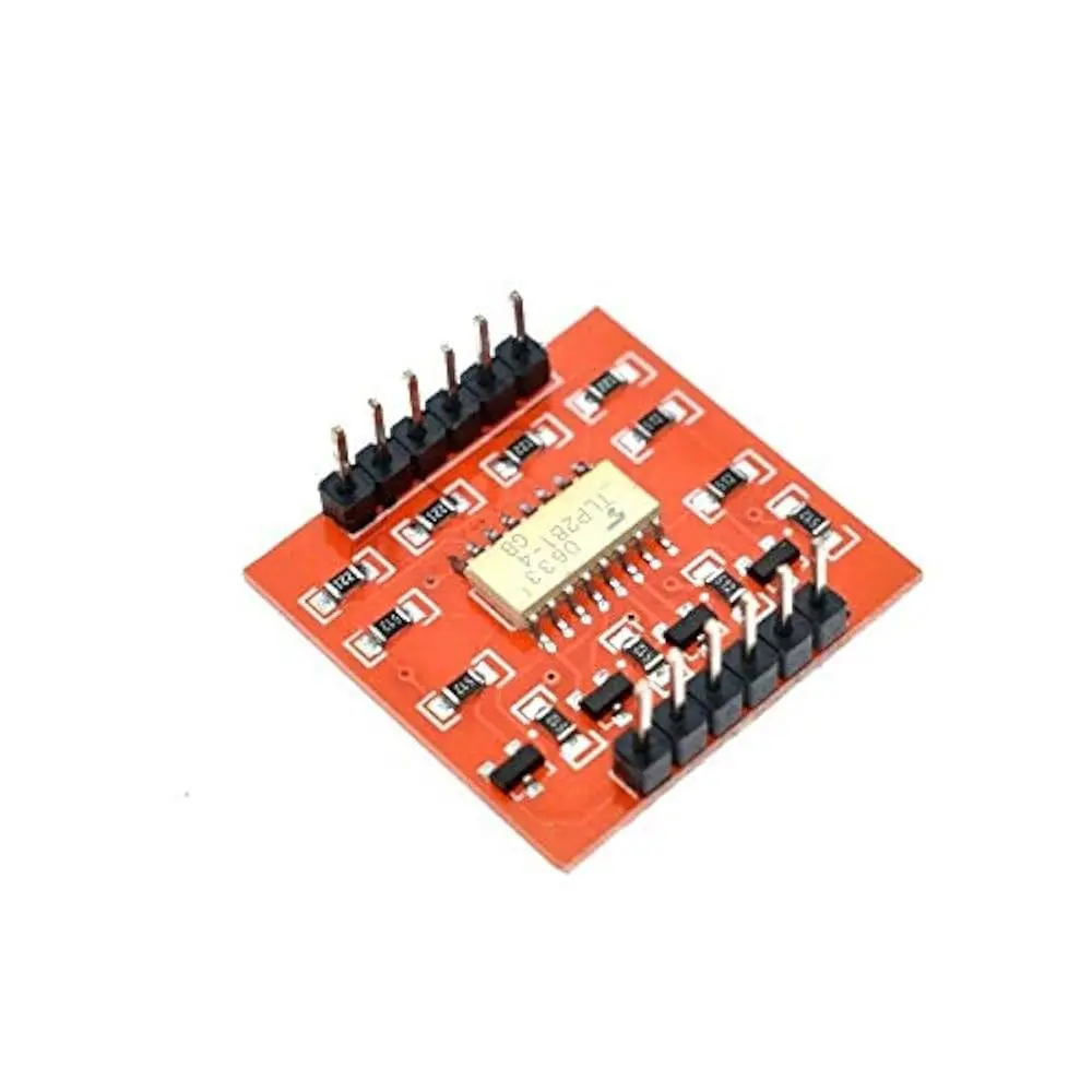
Features:
- Four Channels: Independent isolation for up to four digital signal pairs.
- High Isolation Voltage: Up to 5,000V RMS for strong protection.
- Compact and Space-Saving: Small footprint suitable for embedded applications.
- Low Power Consumption: Ideal for energy-efficient designs.
- High-Speed Transmission: Fast response for real-time digital systems.
- Low Coupling Capacitance: Minimizes signal distortion.
- Wide Operating Temperature: Operates reliably in harsh environments.
- RoHS Compliant: Meets environmental safety standards.
- Highly Reliable: Long operating life and low failure rate.
- Easy Integration: Simple interface for quick setup.
Principle of Work:
- Voltage applied to the input pin powers the internal LED.
- The emitted light activates a phototransistor across the barrier.
- The phototransistor switches, reproducing the input signal on the output side.
- There is no electrical connection between input and output—ensuring full isolation.
Pinout of the Module:
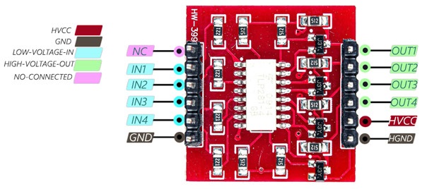
- HVCC: Output base voltage (max 24V)
- HGND: Output ground
- GND: Input ground
- IN1–IN4: Digital input pins 1–4
- OUT1–OUT4: Isolated output pins 1–4
- NC: Not connected
Applications:
- Industrial control systems
- Motor driver and automation circuits
- Medical equipment (isolation)
- Digital signal isolation in microcontrollers
- Audio circuits (noise suppression)
- Power supply isolation
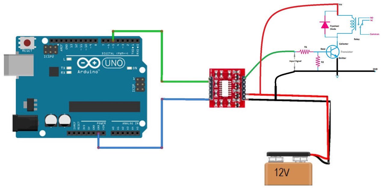
Example Circuit:
This example shows how to interface the TLP281 with an Arduino and a relay module.
Arduino Example Code:
int inputPin = 5;
int relayPin = 10;
int state = 0;

void setup() {
  pinMode(inputPin, INPUT);
  pinMode(relayPin, OUTPUT);
  Serial.begin(9600);
}

void loop() {
  if (Serial.available() > 0) {
    state = Serial.read() - '0'; // Read value from Serial Monitor
  }

  digitalWrite(relayPin, LOW); // Default OFF

  if (digitalRead(inputPin) == HIGH && state == 1) {
    digitalWrite(relayPin, HIGH); // Turn ON relay
  }

  delay(100);
}
Upload this sketch to your Arduino. Open the Serial Monitor and send “1” to turn the relay ON or “0” to turn it OFF.
Technical Specifications:
- Isolation Voltage: 5,000V RMS (min)
- Input Voltage: 5V DC (max)
- Output Voltage: 55V DC (max)
- Output Current: 50mA (max)
- Operating Temp Range: -40°C to +110°C
- Storage Temp Range: -55°C to +125°C
- Rise/Fall Time: 18ns (max)
- Propagation Delay: 100ns (max)
- Power Consumption: 0.2mW (typical)
- Insulation Resistance: 1012 ohms (min)
- CMTI: 10kV/μs (min)
- PCB Size: 25 x 24 mm
Comparison with MOC3041:
| Feature | TLP281 | MOC3041 |
|---|---|---|
| Number of Channels | 4 | 1 |
| Isolation Voltage | 5000V RMS | 2500V RMS |
| Output Type | Phototransistor | Triac |
| Trigger Current | 16mA (max) | 50mA (max) |
| Best Use Case | Digital signal isolation | AC load switching |
Resources:
Features:
- Four Channels: Independent isolation for up to four digital signal pairs.
- High Isolation Voltage: Up to 5,000V RMS for strong protection.
- Compact and Space-Saving: Small footprint suitable for embedded applications.
- Low Power Consumption: Ideal for energy-efficient designs.
- High-Speed Transmission: Fast response for real-time digital systems.
- Low Coupling Capacitance: Minimizes signal distortion.
- Wide Operating Temperature: Operates reliably in harsh environments.
- RoHS Compliant: Meets environmental safety standards.
- Highly Reliable: Long operating life and low failure rate.
- Easy Integration: Simple interface for quick setup.
Principle of Work:
- Voltage applied to the input pin powers the internal LED.
- The emitted light activates a phototransistor across the barrier.
- The phototransistor switches, reproducing the input signal on the output side.
- There is no electrical connection between input and output—ensuring full isolation.
Pinout of the Module:
- HVCC: Output base voltage (max 24V)
- HGND: Output ground
- GND: Input ground
- IN1–IN4: Digital input pins 1–4
- OUT1–OUT4: Isolated output pins 1–4
- NC: Not connected
Applications:
- Industrial control systems
- Motor driver and automation circuits
- Medical equipment (isolation)
- Digital signal isolation in microcontrollers
- Audio circuits (noise suppression)
- Power supply isolation
Example Circuit:
This example shows how to interface the TLP281 with an Arduino and a relay module.
Arduino Example Code:
int inputPin = 5;
int relayPin = 10;
int state = 0;

void setup() {
  pinMode(inputPin, INPUT);
  pinMode(relayPin, OUTPUT);
  Serial.begin(9600);
}

void loop() {
  if (Serial.available() > 0) {
    state = Serial.read() - '0'; // Read value from Serial Monitor
  }

  digitalWrite(relayPin, LOW); // Default OFF

  if (digitalRead(inputPin) == HIGH && state == 1) {
    digitalWrite(relayPin, HIGH); // Turn ON relay
  }

  delay(100);
}
Upload this sketch to your Arduino. Open the Serial Monitor and send “1” to turn the relay ON or “0” to turn it OFF.
Technical Specifications:
- Isolation Voltage: 5,000V RMS (min)
- Input Voltage: 5V DC (max)
- Output Voltage: 55V DC (max)
- Output Current: 50mA (max)
- Operating Temp Range: -40°C to +110°C
- Storage Temp Range: -55°C to +125°C
- Rise/Fall Time: 18ns (max)
- Propagation Delay: 100ns (max)
- Power Consumption: 0.2mW (typical)
- Insulation Resistance: 1012 ohms (min)
- CMTI: 10kV/μs (min)
- PCB Size: 25 x 24 mm
Comparison with MOC3041:
| Feature | TLP281 | MOC3041 |
|---|---|---|
| Number of Channels | 4 | 1 |
| Isolation Voltage | 5000V RMS | 2500V RMS |
| Output Type | Phototransistor | Triac |
| Trigger Current | 16mA (max) | 50mA (max) |
| Best Use Case | Digital signal isolation | AC load switching |