Features
- Compact and easy-to-use dual motor driver module
- Controls two DC motors independently
- Maximum motor voltage up to 15V
- Maximum output current of 1.2A per channel
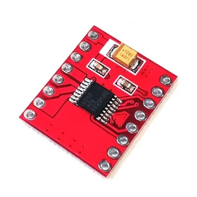
- Based on the high-efficiency TB6612FNG dual H-bridge motor driver IC
- Built-in thermal shutdown protection
- PWM-based speed control and digital direction control
- Standby pin to disable motor outputs and reduce power consumption
- Screw terminals for secure motor and power connections
- Compatible with Arduino, Raspberry Pi, and other microcontrollers
Principle of Work
The module operates using a dual H-bridge configuration implemented by the TB6612FNG IC. An H-bridge consists of four switching elements that allow the polarity of the voltage applied to a motor to be reversed, enabling clockwise and counter-clockwise rotation.
The microcontroller supplies PWM signals to control motor speed and digital signals to control motor direction. When a PWM signal is applied, the driver regulates the effective voltage delivered to the motor, adjusting its speed. Direction control pins determine the polarity of the applied voltage, while the standby pin enables or disables the motor outputs to conserve power when the motors are idle.
Pinout of the Module
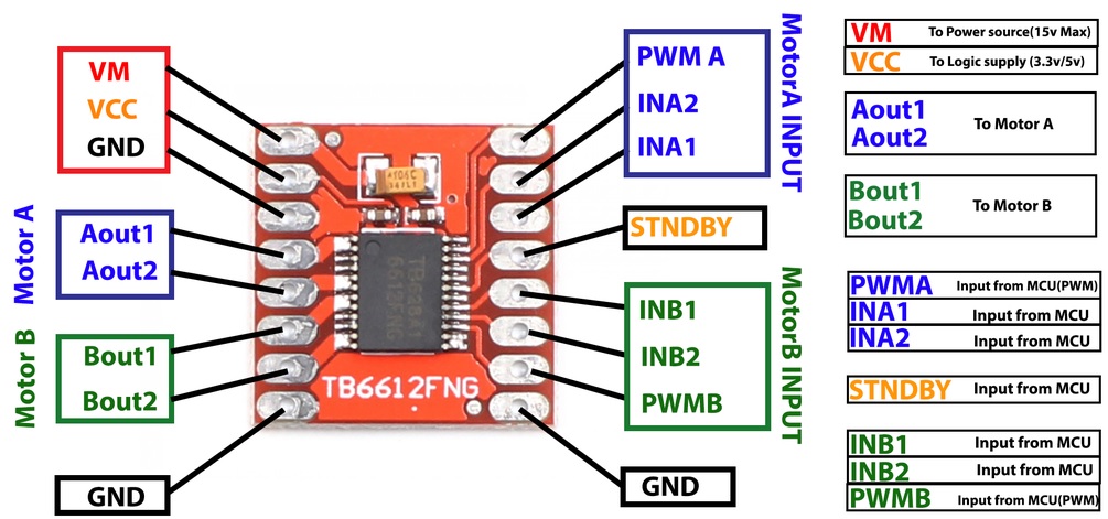
- VM – Motor power supply input
- VCC – Logic power supply input
- GND – Ground (all GND pins are internally connected)
- A1 – Motor A positive terminal
- A2 – Motor A negative terminal
- B1 – Motor B positive terminal
- B2 – Motor B negative terminal
- PWMA – PWM speed control for Motor A
- PWMB – PWM speed control for Motor B
- AIN1 – Direction control input for Motor A
- AIN2 – Direction control input for Motor A
- BIN1 – Direction control input for Motor B
- BIN2 – Direction control input for Motor B
- STBY – Standby control pin, must be HIGH to enable the driver
Applications
- Robotics and mobile robots
- Automation systems
- Educational motor control projects
- Smart vehicles and tracking robots
- DIY motion control applications
Circuit
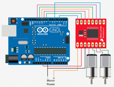
- Motor A connected between A01 and A02
- Motor B connected between B01 and B02
- STBY used to enable or disable the module
- PWMA and PWMB used for speed control
- AIN and BIN pins used for direction control
- VCC supplied from logic source, VM from motor power source
- All grounds must be common
Library
No library is required for this module.
Code
The following Arduino example code demonstrates how to control two DC motors using the TB6612FNG motor driver module.
const int STBY = 10;

// Motor A
const int PWMA = 3;
const int AIN1 = 9;
const int AIN2 = 8;

// Motor B
const int PWMB = 5;
const int BIN1 = 11;
const int BIN2 = 12;

void setup() {
  pinMode(STBY, OUTPUT);

  pinMode(PWMA, OUTPUT);
  pinMode(AIN1, OUTPUT);
  pinMode(AIN2, OUTPUT);

  pinMode(PWMB, OUTPUT);
  pinMode(BIN1, OUTPUT);
  pinMode(BIN2, OUTPUT);

  stop();
}

void loop() {
  move(PWMA, AIN1, AIN2, 255, 1);
  move(PWMB, BIN1, BIN2, 255, 1);
  delay(1000);

  stop();
  delay(250);

  move(PWMA, AIN1, AIN2, 128, 0);
  move(PWMB, BIN1, BIN2, 128, 0);
  delay(1000);

  stop();
  delay(250);
}

void move(int speedPin, int inPin1, int inPin2, int speed, int direction) {
  digitalWrite(STBY, HIGH);

  boolean inPinA = LOW;
  boolean inPinB = HIGH;

  if (direction == 1) {
    inPinA = HIGH;
    inPinB = LOW;
  }

  digitalWrite(inPin1, inPinA);
  digitalWrite(inPin2, inPinB);
  analogWrite(speedPin, speed);
}

void stop() {
  digitalWrite(STBY, LOW);
}
Technical Specifications
- Motor supply voltage (VM): up to 15V
- Logic supply voltage (VCC): 2.7V to 5.5V
- Output current: 1.2A average, 3.2A peak
- Standby mode for power saving
- Supports CW, CCW, brake, and stop modes
- Built-in thermal shutdown and low-voltage detection
- 0.1 inch pin spacing
- On-board filtering capacitors
- Dimensions: 0.8 x 0.8 inches
Resources
- TB6612FNG datasheet, PDF file
- Motor Driver-Dual TB6612FNG, GitHub
- TB6612FNG H-Bridge with Arduino – Better Than L298N?, tutorial by DroneBot workshop
- Controlling DC motors with TB6612FNG breakout board for Arduino, tutorial by Arduino Platform.com
- Driving Small Motors With the TB6612FNG, by ArtisTech in Instructables
Comparisons
The TB6612FNG and DRV8833 are both popular dual H-bridge motor drivers. The TB6612FNG supports higher motor voltages up to 15V and offers higher current capacity, making it suitable for larger motors. The DRV8833 operates at lower voltages with reduced heat generation, making it more suitable for low-power applications.
Features
- Compact and easy-to-use dual motor driver module
- Controls two DC motors independently
- Maximum motor voltage up to 15V
- Maximum output current of 1.2A per channel
- Based on the high-efficiency TB6612FNG dual H-bridge motor driver IC
- Built-in thermal shutdown protection
- PWM-based speed control and digital direction control
- Standby pin to disable motor outputs and reduce power consumption
- Screw terminals for secure motor and power connections
- Compatible with Arduino, Raspberry Pi, and other microcontrollers
Principle of Work
The module operates using a dual H-bridge configuration implemented by the TB6612FNG IC. An H-bridge consists of four switching elements that allow the polarity of the voltage applied to a motor to be reversed, enabling clockwise and counter-clockwise rotation.
The microcontroller supplies PWM signals to control motor speed and digital signals to control motor direction. When a PWM signal is applied, the driver regulates the effective voltage delivered to the motor, adjusting its speed. Direction control pins determine the polarity of the applied voltage, while the standby pin enables or disables the motor outputs to conserve power when the motors are idle.
Pinout of the Module
- VM – Motor power supply input
- VCC – Logic power supply input
- GND – Ground (all GND pins are internally connected)
- A1 – Motor A positive terminal
- A2 – Motor A negative terminal
- B1 – Motor B positive terminal
- B2 – Motor B negative terminal
- PWMA – PWM speed control for Motor A
- PWMB – PWM speed control for Motor B
- AIN1 – Direction control input for Motor A
- AIN2 – Direction control input for Motor A
- BIN1 – Direction control input for Motor B
- BIN2 – Direction control input for Motor B
- STBY – Standby control pin, must be HIGH to enable the driver
Applications
- Robotics and mobile robots
- Automation systems
- Educational motor control projects
- Smart vehicles and tracking robots
- DIY motion control applications
Circuit
- Motor A connected between A01 and A02
- Motor B connected between B01 and B02
- STBY used to enable or disable the module
- PWMA and PWMB used for speed control
- AIN and BIN pins used for direction control
- VCC supplied from logic source, VM from motor power source
- All grounds must be common
Library
No library is required for this module.
Code
The following Arduino example code demonstrates how to control two DC motors using the TB6612FNG motor driver module.
const int STBY = 10;

// Motor A
const int PWMA = 3;
const int AIN1 = 9;
const int AIN2 = 8;

// Motor B
const int PWMB = 5;
const int BIN1 = 11;
const int BIN2 = 12;

void setup() {
  pinMode(STBY, OUTPUT);

  pinMode(PWMA, OUTPUT);
  pinMode(AIN1, OUTPUT);
  pinMode(AIN2, OUTPUT);

  pinMode(PWMB, OUTPUT);
  pinMode(BIN1, OUTPUT);
  pinMode(BIN2, OUTPUT);

  stop();
}

void loop() {
  move(PWMA, AIN1, AIN2, 255, 1);
  move(PWMB, BIN1, BIN2, 255, 1);
  delay(1000);

  stop();
  delay(250);

  move(PWMA, AIN1, AIN2, 128, 0);
  move(PWMB, BIN1, BIN2, 128, 0);
  delay(1000);

  stop();
  delay(250);
}

void move(int speedPin, int inPin1, int inPin2, int speed, int direction) {
  digitalWrite(STBY, HIGH);

  boolean inPinA = LOW;
  boolean inPinB = HIGH;

  if (direction == 1) {
    inPinA = HIGH;
    inPinB = LOW;
  }

  digitalWrite(inPin1, inPinA);
  digitalWrite(inPin2, inPinB);
  analogWrite(speedPin, speed);
}

void stop() {
  digitalWrite(STBY, LOW);
}
Technical Specifications
- Motor supply voltage (VM): up to 15V
- Logic supply voltage (VCC): 2.7V to 5.5V
- Output current: 1.2A average, 3.2A peak
- Standby mode for power saving
- Supports CW, CCW, brake, and stop modes
- Built-in thermal shutdown and low-voltage detection
- 0.1 inch pin spacing
- On-board filtering capacitors
- Dimensions: 0.8 x 0.8 inches
Resources
- TB6612FNG datasheet, PDF file
- Motor Driver-Dual TB6612FNG, GitHub
- TB6612FNG H-Bridge with Arduino – Better Than L298N?, tutorial by DroneBot workshop
- Controlling DC motors with TB6612FNG breakout board for Arduino, tutorial by Arduino Platform.com
- Driving Small Motors With the TB6612FNG, by ArtisTech in Instructables
Comparisons
The TB6612FNG and DRV8833 are both popular dual H-bridge motor drivers. The TB6612FNG supports higher motor voltages up to 15V and offers higher current capacity, making it suitable for larger motors. The DRV8833 operates at lower voltages with reduced heat generation, making it more suitable for low-power applications.