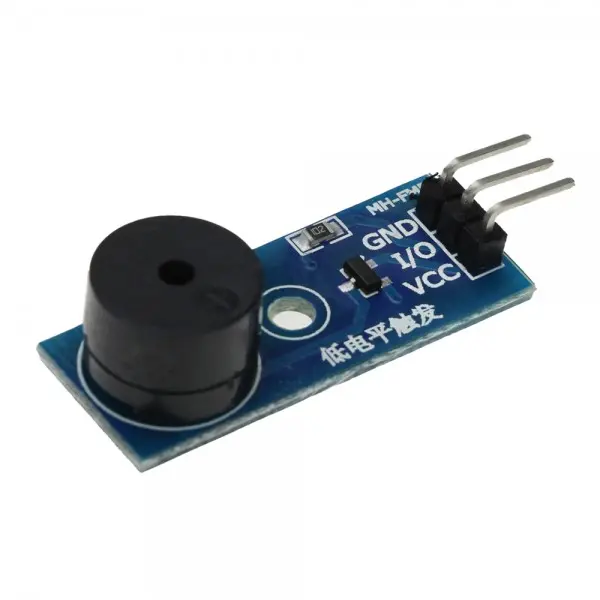
Features
- Active buzzer module for simple ON/OFF sound generation.
- Uses an S8550 transistor for buzzer control.
- Operates from 3.3V to 5V.
- Compatible with both 3.3V and 5V microcontroller systems.
- Can be controlled using a standard digital output signal.
- Compact PCB design measuring approximately 3.3 cm × 1.3 cm.
- Pre-drilled mounting holes for convenient installation.
- Simple three-pin interface for easy wiring.
- Suitable for alarms, notifications, security systems, and sound-feedback applications.
Principle of Operation
An active buzzer contains an internal oscillator that generates the required audio signal. Therefore, unlike a passive buzzer, it does not require an externally generated frequency signal to produce a tone.
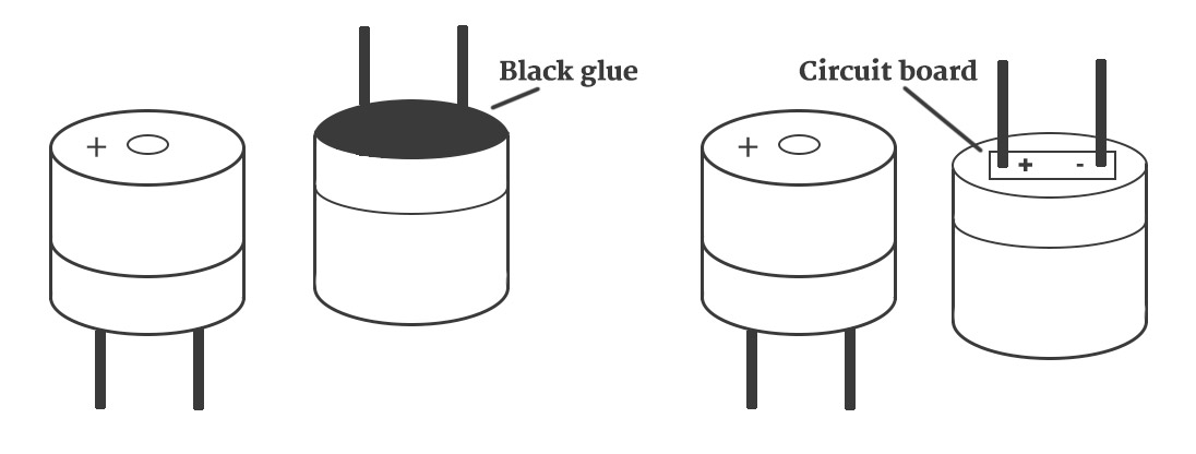
The microcontroller controls the module through its IN signal pin. When the control signal activates the S8550 transistor, current flows through the buzzer and the internal oscillator produces an audible tone. When the control signal is deactivated, the buzzer stops producing sound. This makes the module particularly convenient for simple audible alerts where only ON/OFF control is required.
Applications
- Arduino alarm projects
- Security and warning systems
- Notification and alert systems
- Microcontroller sound indicators
- IoT device notifications
- Robotics projects
- Access-control systems
- Electronic equipment status indicators
- Educational electronics projects
- DIY embedded systems
Pinout
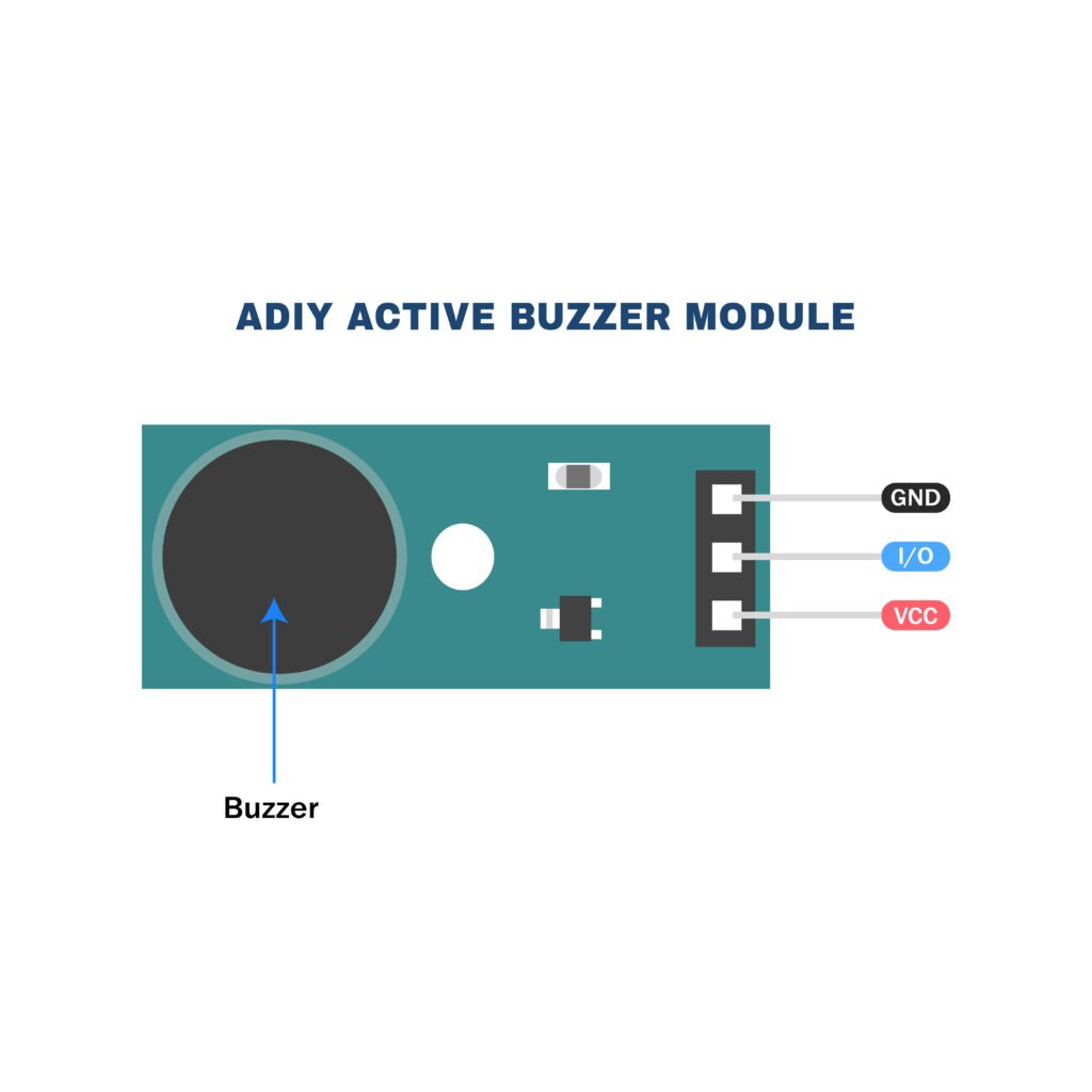
| Pin | Label | Function |
|---|---|---|
| 1 | VCC | Positive power supply, 3.3V–5V |
| 2 | GND | Ground connection |
| 3 | IN | Digital control signal input |
Wiring
The module can be controlled directly from a suitable Arduino digital output. Connect the power and ground pins to the Arduino, then connect the IN pin to a digital output such as D8.

| Buzzer Module | Arduino Connection |
|---|---|
| VCC | Arduino 5V or 3.3V |
| GND | Arduino GND |
| IN | Arduino Digital Pin D8 |
Set the Arduino output pin HIGH to activate the buzzer and LOW to deactivate it.
Arduino Example
int buzzer = 8;

void setup() {
pinMode(buzzer, OUTPUT);
}

void loop() {
digitalWrite(buzzer, HIGH);
delay(500);

digitalWrite(buzzer, LOW);
delay(500);
}Specifications
| Product Name | Active Buzzer Module |
| Buzzer Type | Active Buzzer |
| Transistor | S8550 |
| Working Voltage | 3.3V–5V DC |
| Control Method | Digital ON/OFF signal |
| Interface | 3-pin header: VCC, GND, IN |
| PCB Dimensions | Approximately 3.3 × 1.3 cm |
Features
- Active buzzer module for simple ON/OFF sound generation.
- Uses an S8550 transistor for buzzer control.
- Operates from 3.3V to 5V.
- Compatible with both 3.3V and 5V microcontroller systems.
- Can be controlled using a standard digital output signal.
- Compact PCB design measuring approximately 3.3 cm × 1.3 cm.
- Pre-drilled mounting holes for convenient installation.
- Simple three-pin interface for easy wiring.
- Suitable for alarms, notifications, security systems, and sound-feedback applications.
Principle of Operation
An active buzzer contains an internal oscillator that generates the required audio signal. Therefore, unlike a passive buzzer, it does not require an externally generated frequency signal to produce a tone.
The microcontroller controls the module through its IN signal pin. When the control signal activates the S8550 transistor, current flows through the buzzer and the internal oscillator produces an audible tone. When the control signal is deactivated, the buzzer stops producing sound. This makes the module particularly convenient for simple audible alerts where only ON/OFF control is required.
Applications
- Arduino alarm projects
- Security and warning systems
- Notification and alert systems
- Microcontroller sound indicators
- IoT device notifications
- Robotics projects
- Access-control systems
- Electronic equipment status indicators
- Educational electronics projects
- DIY embedded systems
Pinout
| Pin | Label | Function |
|---|---|---|
| 1 | VCC | Positive power supply, 3.3V–5V |
| 2 | GND | Ground connection |
| 3 | IN | Digital control signal input |
Wiring
The module can be controlled directly from a suitable Arduino digital output. Connect the power and ground pins to the Arduino, then connect the IN pin to a digital output such as D8.
| Buzzer Module | Arduino Connection |
|---|---|
| VCC | Arduino 5V or 3.3V |
| GND | Arduino GND |
| IN | Arduino Digital Pin D8 |
Set the Arduino output pin HIGH to activate the buzzer and LOW to deactivate it.
Arduino Example
int buzzer = 8;

void setup() {
pinMode(buzzer, OUTPUT);
}

void loop() {
digitalWrite(buzzer, HIGH);
delay(500);

digitalWrite(buzzer, LOW);
delay(500);
}
Specifications
| Product Name | Active Buzzer Module |
| Buzzer Type | Active Buzzer |
| Transistor | S8550 |
| Working Voltage | 3.3V–5V DC |
| Control Method | Digital ON/OFF signal |
| Interface | 3-pin header: VCC, GND, IN |
| PCB Dimensions | Approximately 3.3 × 1.3 cm |