Features:
- PCB Color: Blue
- Configured as Low Trigger.
- There are four fixed screw holes at each corner of the board, easy for install and fix. The diameter of the hole is 3.1mm
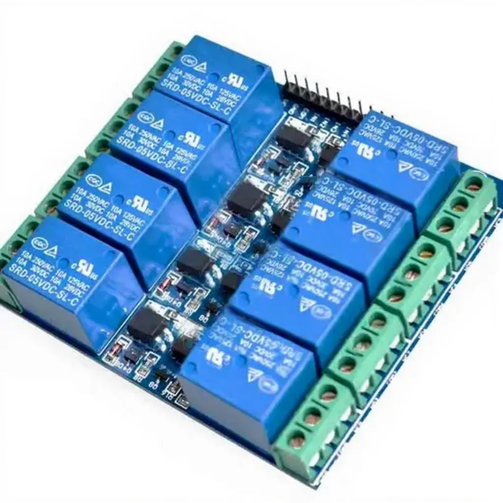
- High-quality Songle Relay is used with single pole double throw, a common terminal, a normally open terminal, and a normally closed terminal
- Optical coupling isolation, good anti-interference.
- Closed at a low level with indicator on, released at a high level with indicator off
- VCC is a system power source, and JD_VCC is a Relay power source. Ship 5V Relay by default. Plug jumper cap to use
- The maximum output of the Relay: DC 30V/10A, AC 250V/10A
Principle of Work:
An iron core is surrounded by a control coil. As shown, the power source is given to the electromagnet through a control switch and through contacts to the load. When current starts flowing through the control coil, the electromagnet starts energizing and thus intensifies the magnetic field. Thus the upper contact arm starts to be attracted to the lower fixed arm and thus closes the contacts causing a short circuit for the power to the load. On the other hand, if the relay was already de-energized when the contacts were closed, then the contact move oppositely and make an open circuit.
As soon as the coil current is off, the movable armature will be returned by a force back to its initial position. This force will be almost equal to half the strength of the magnetic force. This force is mainly provided by two factors. They are spring and also gravity. Relays are mainly made for two basic operations. One is low voltage application and the other is high voltage. For low-voltage applications. and low-level triggered functionality will allow the current to go through the power line when the control signal is GND or close. optocoupler on the other hand makes real photo isolation between the relay and the MCU which is very good to minimize the distortion from the other side
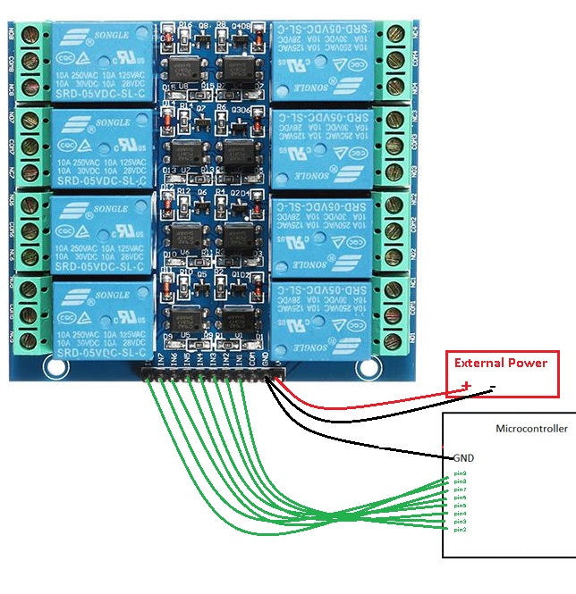
Pinout of the Module:

Applications:
- Relay Drive from External Contacts.
- LED Series and Parallel Connections.
- Electronic Circuit Drive by Means of a Relay.
- Home automation
- Battery backup
- High current load switching
Circuit:
in this example, we will blink a 220v lamp for 1sec and shoot it down for 1sec.
Library:
This Module doesn't need a library to work.
Code:
void setup() {
 // initialize digital pin LED_BUILTIN as an output.
 pinMode(2, OUTPUT);
 pinMode(3, OUTPUT);
 pinMode(4, OUTPUT);
 pinMode(5, OUTPUT);
 pinMode(6, OUTPUT);
 pinMode(7, OUTPUT);
 pinMode(8, OUTPUT);
 pinMode(9, OUTPUT);
digitalWrite(2, HIGH);
digitalWrite(3, HIGH);
digitalWrite(4, HIGH);
digitalWrite(5, HIGH);
digitalWrite(6, HIGH);
digitalWrite(7, HIGH);
digitalWrite(8, HIGH);
digitalWrite(9, HIGH);
}
// the loop function runs over and over again forever
void loop() {
 digitalWrite(2, LOW); // turn the LED ON by making the voltage LOW delay(1000);
 delay(1000); // wait for a second
 digitalWrite(3, LOW); // turn the LED ON by making the voltage LOW delay(1000);
 delay(1000); // wait for a second
digitalWrite(4, LOW); // turn the LED ON by making the voltage LOW delay(1000);
 delay(1000); // wait for a second
digitalWrite(5, LOW); // turn the LED ON by making the voltage LOW delay(1000);
 delay(1000); // wait for a second
 digitalWrite(6, LOW); // turn the LED ON by making the voltage LOW delay(1000);
 delay(1000); // wait for a second
 digitalWrite(7, LOW); // turn the LED ON by making the voltage LOW delay(1000);
 delay(1000); // wait for a second
digitalWrite(8, LOW); // turn the LED ON by making the voltage LOW delay(1000);
 delay(1000); // wait for a second
digitalWrite(9, LOW); // turn the LED ON by making the voltage LOW delay(1000);
 delay(1000); // wait for a second
 digitalWrite(2, HIGH); // turn the offon (HIGH is the voltage level)
 delay(1000); // wait for a second
 digitalWrite(3, HIGH); // turn the offon (HIGH is the voltage level)
 delay(1000); // wait for a second
 digitalWrite(4, HIGH); // turn the offon (HIGH is the voltage level)
 delay(1000); // wait for a second
 digitalWrite(5, HIGH); // turn the offon (HIGH is the voltage level)
 delay(1000); // wait for a second
 digitalWrite(6, HIGH); // turn the offon (HIGH is the voltage level)
 delay(1000); // wait for a second
 digitalWrite(7, HIGH); // turn the offon (HIGH is the voltage level)
 delay(1000); // wait for a second
 digitalWrite(8, HIGH); // turn the offon (HIGH is the voltage level)
 delay(1000); // wait for a second
 digitalWrite(9, HIGH); // turn the offon (HIGH is the voltage level)
 delay(1000); // wait for a second
}
Technical Details:
- 8 Channel
- Maximum switching voltage: 250VAC / 30VDC
- Maximum switching current: 10A
- Module operating voltage: 5V
Comparisons:
The relays in this board have been arranged in a way that makes the board compact and lowers the space needed for 8 relays, using an Active Low Triggered Relay Module comes with a price that you need to use a current to keep the application off on the other side of the relay or you can use this board with the application where needed to be on all the time and turn it off less often or simple you can connect the application on the NO side instead of the normal connecting. the optocoupler on the other hand is very useful this device lowers the distortion from the power lines and makes the circuit more isolated and better than the boards where no such a device is included so you need always to connect the GND of the MCU GND of the circuit which is not very good idea sometimes.
This kind of relay board has so many advantages like being able to withstand large inrush currents and high mechanical structure reliability, not being susceptible to the external electromagnetic environment, and being able to carry high voltage, and high current load but still, it has multiple disadvantages to the SSR Boards that they are slower than SSRs at 5 to 15ms and it has a larger package size, are not suitable for small projects and electromechanical relays tend to have a shorter life than other types of relays due to mechanical wear if you interested in SSRs you can get it from here
Features:
- PCB Color: Blue
- Configured as Low Trigger.
- There are four fixed screw holes at each corner of the board, easy for install and fix. The diameter of the hole is 3.1mm
- High-quality Songle Relay is used with single pole double throw, a common terminal, a normally open terminal, and a normally closed terminal
- Optical coupling isolation, good anti-interference.
- Closed at a low level with indicator on, released at a high level with indicator off
- VCC is a system power source, and JD_VCC is a Relay power source. Ship 5V Relay by default. Plug jumper cap to use
- The maximum output of the Relay: DC 30V/10A, AC 250V/10A
Principle of Work:
An iron core is surrounded by a control coil. As shown, the power source is given to the electromagnet through a control switch and through contacts to the load. When current starts flowing through the control coil, the electromagnet starts energizing and thus intensifies the magnetic field. Thus the upper contact arm starts to be attracted to the lower fixed arm and thus closes the contacts causing a short circuit for the power to the load. On the other hand, if the relay was already de-energized when the contacts were closed, then the contact move oppositely and make an open circuit.
As soon as the coil current is off, the movable armature will be returned by a force back to its initial position. This force will be almost equal to half the strength of the magnetic force. This force is mainly provided by two factors. They are spring and also gravity. Relays are mainly made for two basic operations. One is low voltage application and the other is high voltage. For low-voltage applications. and low-level triggered functionality will allow the current to go through the power line when the control signal is GND or close. optocoupler on the other hand makes real photo isolation between the relay and the MCU which is very good to minimize the distortion from the other side
Pinout of the Module:
Applications:
- Relay Drive from External Contacts.
- LED Series and Parallel Connections.
- Electronic Circuit Drive by Means of a Relay.
- Home automation
- Battery backup
- High current load switching
Circuit:
in this example, we will blink a 220v lamp for 1sec and shoot it down for 1sec.
Library:
This Module doesn't need a library to work.
Code:
void setup() {
 // initialize digital pin LED_BUILTIN as an output.
 pinMode(2, OUTPUT);
 pinMode(3, OUTPUT);
 pinMode(4, OUTPUT);
 pinMode(5, OUTPUT);
 pinMode(6, OUTPUT);
 pinMode(7, OUTPUT);
 pinMode(8, OUTPUT);
 pinMode(9, OUTPUT);
digitalWrite(2, HIGH);
digitalWrite(3, HIGH);
digitalWrite(4, HIGH);
digitalWrite(5, HIGH);
digitalWrite(6, HIGH);
digitalWrite(7, HIGH);
digitalWrite(8, HIGH);
digitalWrite(9, HIGH);
}
// the loop function runs over and over again forever
void loop() {
 digitalWrite(2, LOW); // turn the LED ON by making the voltage LOW delay(1000);
 delay(1000); // wait for a second
 digitalWrite(3, LOW); // turn the LED ON by making the voltage LOW delay(1000);
 delay(1000); // wait for a second
digitalWrite(4, LOW); // turn the LED ON by making the voltage LOW delay(1000);
 delay(1000); // wait for a second
digitalWrite(5, LOW); // turn the LED ON by making the voltage LOW delay(1000);
 delay(1000); // wait for a second
 digitalWrite(6, LOW); // turn the LED ON by making the voltage LOW delay(1000);
 delay(1000); // wait for a second
 digitalWrite(7, LOW); // turn the LED ON by making the voltage LOW delay(1000);
 delay(1000); // wait for a second
digitalWrite(8, LOW); // turn the LED ON by making the voltage LOW delay(1000);
 delay(1000); // wait for a second
digitalWrite(9, LOW); // turn the LED ON by making the voltage LOW delay(1000);
 delay(1000); // wait for a second
 digitalWrite(2, HIGH); // turn the offon (HIGH is the voltage level)
 delay(1000); // wait for a second
 digitalWrite(3, HIGH); // turn the offon (HIGH is the voltage level)
 delay(1000); // wait for a second
 digitalWrite(4, HIGH); // turn the offon (HIGH is the voltage level)
 delay(1000); // wait for a second
 digitalWrite(5, HIGH); // turn the offon (HIGH is the voltage level)
 delay(1000); // wait for a second
 digitalWrite(6, HIGH); // turn the offon (HIGH is the voltage level)
 delay(1000); // wait for a second
 digitalWrite(7, HIGH); // turn the offon (HIGH is the voltage level)
 delay(1000); // wait for a second
 digitalWrite(8, HIGH); // turn the offon (HIGH is the voltage level)
 delay(1000); // wait for a second
 digitalWrite(9, HIGH); // turn the offon (HIGH is the voltage level)
 delay(1000); // wait for a second
}
Technical Details:
- 8 Channel
- Maximum switching voltage: 250VAC / 30VDC
- Maximum switching current: 10A
- Module operating voltage: 5V
Comparisons:
The relays in this board have been arranged in a way that makes the board compact and lowers the space needed for 8 relays, using an Active Low Triggered Relay Module comes with a price that you need to use a current to keep the application off on the other side of the relay or you can use this board with the application where needed to be on all the time and turn it off less often or simple you can connect the application on the NO side instead of the normal connecting. the optocoupler on the other hand is very useful this device lowers the distortion from the power lines and makes the circuit more isolated and better than the boards where no such a device is included so you need always to connect the GND of the MCU GND of the circuit which is not very good idea sometimes.
This kind of relay board has so many advantages like being able to withstand large inrush currents and high mechanical structure reliability, not being susceptible to the external electromagnetic environment, and being able to carry high voltage, and high current load but still, it has multiple disadvantages to the SSR Boards that they are slower than SSRs at 5 to 15ms and it has a larger package size, are not suitable for small projects and electromechanical relays tend to have a shorter life than other types of relays due to mechanical wear if you interested in SSRs you can get it from here