Features:
- Good in safety. In power systems and high voltage systems, the lower current can control the higher one.
- 1-channel high voltage system output, meeting the needs of single-channel control
- Wide range of controllable voltage.
- Being able to control high load current, which can reach 240V, 10A
- With a normally-open (NO) contact and a normally-closed (NC) contacts
Principle of Work:
An iron core is surrounded by a control coil. As shown, the power source is given to the electromagnet through a control switch and through contacts to the load. When current starts flowing through the control coil, the electromagnet starts energizing and thus intensifies the magnetic field. Thus the upper contact arm starts to be attracted to the lower fixed arm and thus closes the contacts causing a short circuit for the power to the load. On the other hand, if the relay was already de-energized when the contacts were closed, then the contact move oppositely and make an open circuit.
As soon as the coil current is off, the movable armature will be returned by a force back to its initial position. This force will be almost equal to half the strength of the magnetic force. This force is mainly provided by two factors. They are spring and also gravity.
Relays are mainly made for two basic operations. One is low voltage application and the other is high voltage. For low-voltage applications
Pinout of the Module:
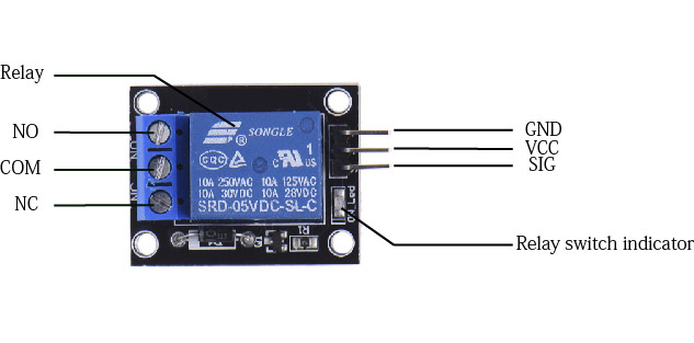
- GND – Connect 0V to this pin.
- SIG – Controls this relay
- VCC – Connect 5V to this pin.
- COM- Common pin
- NC- Normally Closed, in which case NC is connected with COM when INT1 is set low and disconnected when INT1 is high
- NO- Normally Open, in which case NO is disconnected with COM1 when INT1 is set low and connected when INT1 is high
Applications:
- Relay Drive from External Contacts.
- LED Series and Parallel Connections.
- Electronic Circuit Drive by Means of a Relay.
- Home automation
- Battery backup
- High current load switching
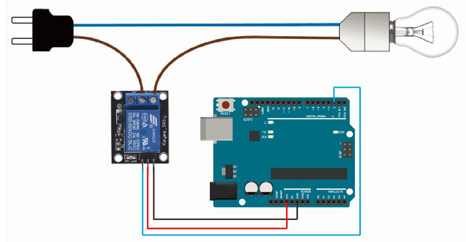
Circuit:
1 distinct load has been connected to the relay NO terminal. the relay common terminal has a live wire connected to it. When the relay is activated, the load is powered and connected to the live wire. This configuration can be reversed by connecting the load to the NC terminal, which keeps the load powered on until the relay is activated. the relay is connected to pin 2 and the trigger is in a high configuration. the power source for the relay is external and the GND of the MCU is connected to the COM pin.
Library:
This Module doesn't need a library to work.
Code:
void setup() {
 // initialize digital pin 2 as an output.
 pinMode(2, OUTPUT);


}
// the loop function runs over and over again forever
void loop() {
 digitalWrite(2, HIGH); // turn the LED ON by making the voltage HIGH delay(1000);
 delay(1000); // wait for a second


 digitalWrite(2, LOW); // turn the on off(LOW is the voltage level)
 delay(1000); // wait for a second


}
Technical Details:
- 1 Channel
- Supply voltage: 5V
- Trigger mode: high trigger
- Voltage: DC 30V or AC 250V
- Current: 10A
- PCB Size:43 x 12 x 10mm
- Item Weight: 14g
Resources:
Features:
- Good in safety. In power systems and high voltage systems, the lower current can control the higher one.
- 1-channel high voltage system output, meeting the needs of single-channel control
- Wide range of controllable voltage.
- Being able to control high load current, which can reach 240V, 10A
- With a normally-open (NO) contact and a normally-closed (NC) contacts
Principle of Work:
An iron core is surrounded by a control coil. As shown, the power source is given to the electromagnet through a control switch and through contacts to the load. When current starts flowing through the control coil, the electromagnet starts energizing and thus intensifies the magnetic field. Thus the upper contact arm starts to be attracted to the lower fixed arm and thus closes the contacts causing a short circuit for the power to the load. On the other hand, if the relay was already de-energized when the contacts were closed, then the contact move oppositely and make an open circuit.
As soon as the coil current is off, the movable armature will be returned by a force back to its initial position. This force will be almost equal to half the strength of the magnetic force. This force is mainly provided by two factors. They are spring and also gravity.
Relays are mainly made for two basic operations. One is low voltage application and the other is high voltage. For low-voltage applications
Pinout of the Module:
- GND – Connect 0V to this pin.
- SIG – Controls this relay
- VCC – Connect 5V to this pin.
- COM- Common pin
- NC- Normally Closed, in which case NC is connected with COM when INT1 is set low and disconnected when INT1 is high
- NO- Normally Open, in which case NO is disconnected with COM1 when INT1 is set low and connected when INT1 is high
Applications:
- Relay Drive from External Contacts.
- LED Series and Parallel Connections.
- Electronic Circuit Drive by Means of a Relay.
- Home automation
- Battery backup
- High current load switching
Circuit:
1 distinct load has been connected to the relay NO terminal. the relay common terminal has a live wire connected to it. When the relay is activated, the load is powered and connected to the live wire. This configuration can be reversed by connecting the load to the NC terminal, which keeps the load powered on until the relay is activated. the relay is connected to pin 2 and the trigger is in a high configuration. the power source for the relay is external and the GND of the MCU is connected to the COM pin.
Library:
This Module doesn't need a library to work.
Code:
void setup() {
 // initialize digital pin 2 as an output.
 pinMode(2, OUTPUT);


}
// the loop function runs over and over again forever
void loop() {
 digitalWrite(2, HIGH); // turn the LED ON by making the voltage HIGH delay(1000);
 delay(1000); // wait for a second


 digitalWrite(2, LOW); // turn the on off(LOW is the voltage level)
 delay(1000); // wait for a second


}
Technical Details:
- 1 Channel
- Supply voltage: 5V
- Trigger mode: high trigger
- Voltage: DC 30V or AC 250V
- Current: 10A
- PCB Size:43 x 12 x 10mm
- Item Weight: 14g