Features
- LM393 comparator chip: Dual independent low-current open-collector outputs for stable digital signal processing.
- Photoelectric sensing: Detects light interruption caused by rotating encoder discs.
- Wide operating voltage: Works with DC 3.3V to 5V.
- LED indicator: Displays power and output signal status.
- PCB mounting holes: Easy installation using M3 screws.
- Compact size: Suitable for space-constrained applications.
Principle of Work
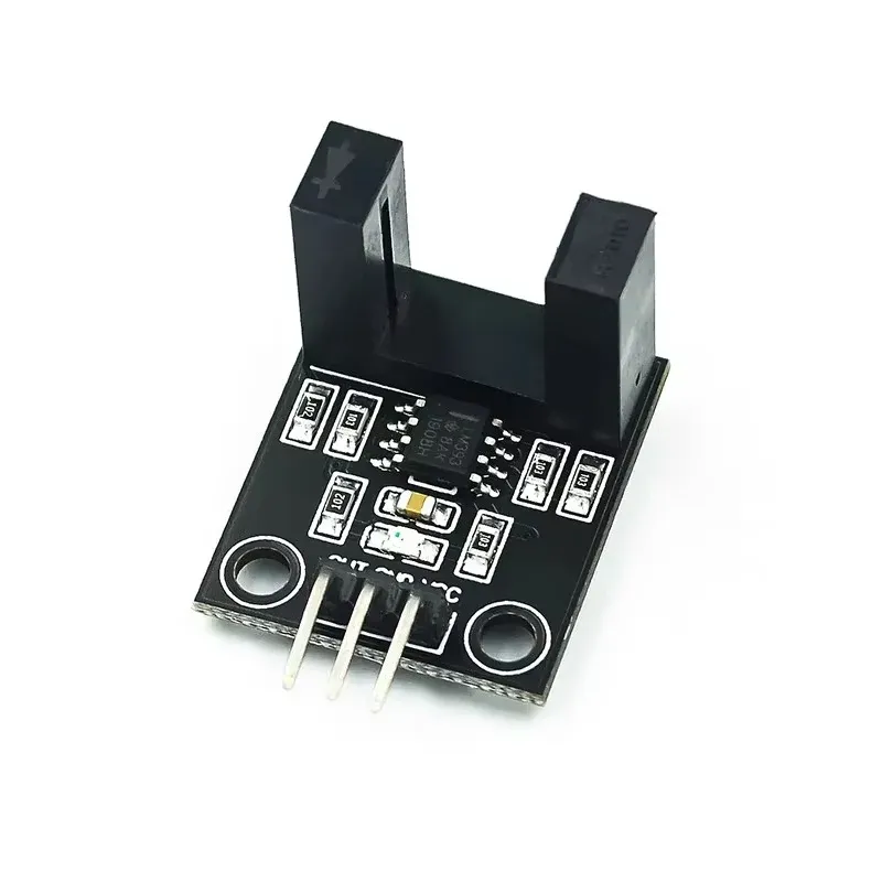
The module consists of an infrared LED emitter and an infrared receiver placed opposite each other within a slot. When a slotted encoder disc rotates through the slot, the infrared beam is alternately blocked and allowed to pass.
Each interruption generates a digital pulse at the output pin. The LM393 comparator processes the signal and outputs a clean HIGH or LOW level. By counting these pulses within a known time interval, the speed of the rotating object can be calculated. The module is powered via VCC and GND, and the OUT pin connects directly to a digital input or interrupt pin on a microcontroller.
Pinout of the Module
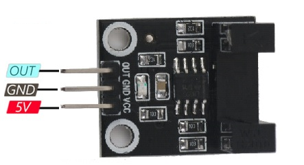
- VCC: Module power supply – 3V to 5.5V
- GND: Ground
- OUT: Digital output signal to microcontroller
Applications
- Motor and wheel speed measurement
- Object detection and counting systems
- Robotics and mobile platforms
- Automation and conveyor belt control
- Automotive speed and position sensing
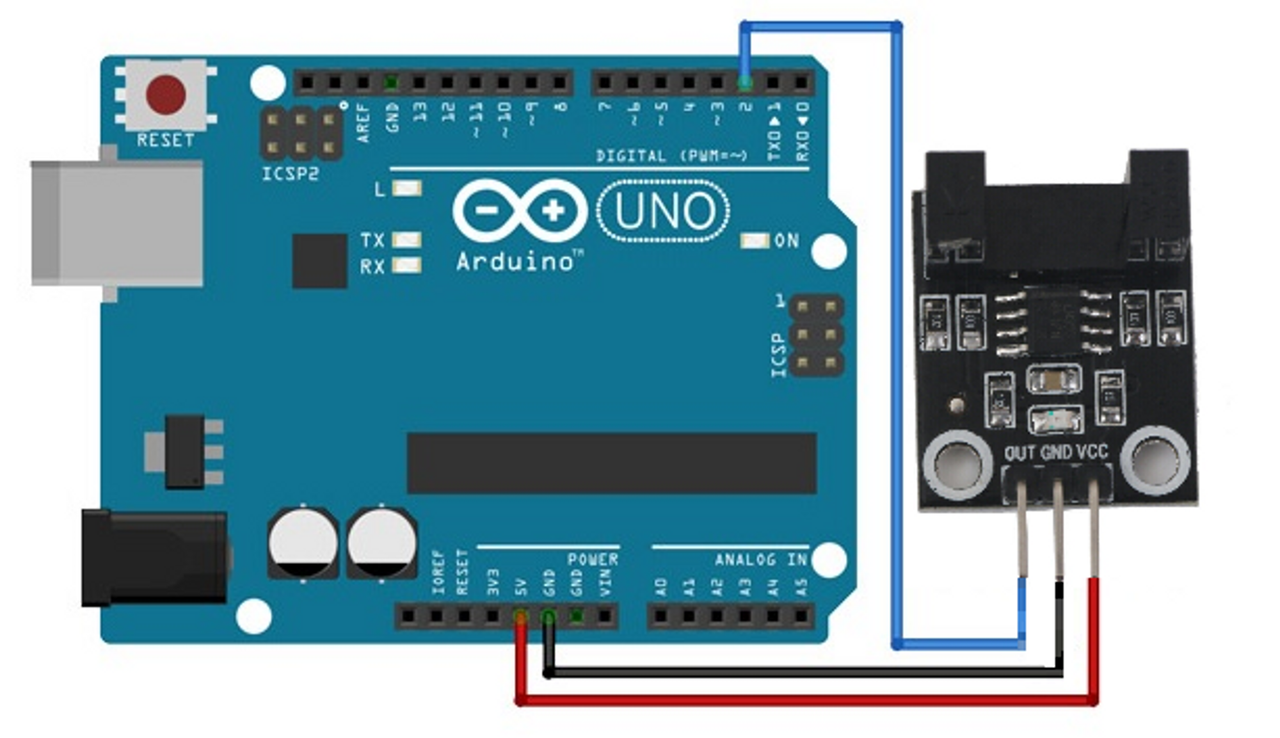
Circuit
Connect the VCC and GND pins of the module to the 5V and GND pins of the Arduino. Connect the OUT pin to digital pin 2 on the Arduino. The digital output can be read directly or used with an interrupt to count pulses accurately.
Library
This module can work without any external library. However, for RPM measurement using timers, the Timer library can be used.
Installation using Arduino IDE:
- Open Arduino IDE.
- Go to Sketch > Include Library > Manage Libraries.
- Search for Timer.
- Install the Timer library.
- Include it in your sketch via Sketch > Include Library > Timer.
Code
// Stepper motor control with ULN2003 driver and Arduino
#include "Stepper.h"

// Define the number of steps per revolution
const int stepsPerRevolution = 2048;

// Initialize the stepper motor
Stepper myStepper(stepsPerRevolution, 11, 10, 9, 8);

void setup() {
// Set the speed of the stepper motor (in RPM)
myStepper.setSpeed(10);
Serial.begin(9600);
}

void loop() {
while (!Serial.available());
char command = Serial.read();

switch (command) {
case 'F':
Serial.println("Moving forward");
myStepper.step(stepsPerRevolution / 4);
break;
case 'B':
Serial.println("Moving backward");
myStepper.step(-stepsPerRevolution / 4);
break;
case 'S':
Serial.println("Stopping");
myStepper.step(0);
break;
default:
Serial.println("Invalid command");
}
} For RPM measurement, the OUT pin can be connected to an interrupt pin using digitalPinToInterrupt(). Each rising edge increments a counter. The RPM is calculated by multiplying the number of pulses counted in one second by 60.
Technical Details
- Optocoupler Model: H2010
- Optocoupler Slot Width: 10mm
- Main Chip: LM393
- Working Voltage: DC 5V
- PCB Mounting Hole Distance: 15mm
- Screw Size: M3
- Module Size: 32mm x 11mm x 20mm
Comparisons
The Encoder Photoelectric Speed Sensor Module LM393 and the FC-03 optical speed sensor both use infrared beam interruption to detect speed. However, the LM393 module provides a digital output with a 3-pin interface, making it simpler for pulse counting applications. The FC-03 module typically offers an analog output and a 4-pin configuration, which can be more suitable for intensity-based measurements. The LM393 module is better suited for precise speed detection and digital pulse counting.
Features
- LM393 comparator chip: Dual independent low-current open-collector outputs for stable digital signal processing.
- Photoelectric sensing: Detects light interruption caused by rotating encoder discs.
- Wide operating voltage: Works with DC 3.3V to 5V.
- LED indicator: Displays power and output signal status.
- PCB mounting holes: Easy installation using M3 screws.
- Compact size: Suitable for space-constrained applications.
Principle of Work
The module consists of an infrared LED emitter and an infrared receiver placed opposite each other within a slot. When a slotted encoder disc rotates through the slot, the infrared beam is alternately blocked and allowed to pass.
Each interruption generates a digital pulse at the output pin. The LM393 comparator processes the signal and outputs a clean HIGH or LOW level. By counting these pulses within a known time interval, the speed of the rotating object can be calculated. The module is powered via VCC and GND, and the OUT pin connects directly to a digital input or interrupt pin on a microcontroller.
Pinout of the Module
- VCC: Module power supply – 3V to 5.5V
- GND: Ground
- OUT: Digital output signal to microcontroller
Applications
- Motor and wheel speed measurement
- Object detection and counting systems
- Robotics and mobile platforms
- Automation and conveyor belt control
- Automotive speed and position sensing
Circuit
Connect the VCC and GND pins of the module to the 5V and GND pins of the Arduino. Connect the OUT pin to digital pin 2 on the Arduino. The digital output can be read directly or used with an interrupt to count pulses accurately.
Library
This module can work without any external library. However, for RPM measurement using timers, the Timer library can be used.
Installation using Arduino IDE:
- Open Arduino IDE.
- Go to Sketch > Include Library > Manage Libraries.
- Search for Timer.
- Install the Timer library.
- Include it in your sketch via Sketch > Include Library > Timer.
Code
// Stepper motor control with ULN2003 driver and Arduino
#include "Stepper.h"

// Define the number of steps per revolution
const int stepsPerRevolution = 2048;

// Initialize the stepper motor
Stepper myStepper(stepsPerRevolution, 11, 10, 9, 8);

void setup() {
// Set the speed of the stepper motor (in RPM)
myStepper.setSpeed(10);
Serial.begin(9600);
}

void loop() {
while (!Serial.available());
char command = Serial.read();

switch (command) {
case 'F':
Serial.println("Moving forward");
myStepper.step(stepsPerRevolution / 4);
break;
case 'B':
Serial.println("Moving backward");
myStepper.step(-stepsPerRevolution / 4);
break;
case 'S':
Serial.println("Stopping");
myStepper.step(0);
break;
default:
Serial.println("Invalid command");
}
}
For RPM measurement, the OUT pin can be connected to an interrupt pin using digitalPinToInterrupt(). Each rising edge increments a counter. The RPM is calculated by multiplying the number of pulses counted in one second by 60.
Technical Details
- Optocoupler Model: H2010
- Optocoupler Slot Width: 10mm
- Main Chip: LM393
- Working Voltage: DC 5V
- PCB Mounting Hole Distance: 15mm
- Screw Size: M3
- Module Size: 32mm x 11mm x 20mm
Comparisons
The Encoder Photoelectric Speed Sensor Module LM393 and the FC-03 optical speed sensor both use infrared beam interruption to detect speed. However, the LM393 module provides a digital output with a 3-pin interface, making it simpler for pulse counting applications. The FC-03 module typically offers an analog output and a 4-pin configuration, which can be more suitable for intensity-based measurements. The LM393 module is better suited for precise speed detection and digital pulse counting.