Features:
- Superior Temp. Stability for Automotive or Industrial Applications
- 4.5 V to 24 V Operation … Needs Only An Unregulated Supply
- Power LED Indicator
- Open-Collector 25 mA Output … Compatible with Digital Logic
- Reverse Battery Protection
- Activate with Small, Commercially Available Permanent Magnets
- Solid-State Reliability
- Small Size
- Resistant to Physical Stress
- Compatible with Arduino
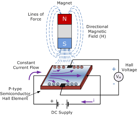
Principle of Work:
When an electric current flows through a conductor, a magnetic field perpendicular to the current direction is created. This magnetic field applies a diagonal force to the moving charge carriers, pushing them to one side of the conductor. Because of the potential difference caused by the pushed outwards charge, a measurable voltage between the two sides of the conductor is produced, which is known as the Hall voltage. The Hall Effect is named after E. H. Hall, who discovered it in 1879. The effect is determined by the conductor's thickness. As a result, the conductor should be very thin.
Because of their unipolar switching characteristics, these devices are ideal for use with a simple bar or rod magnet. When the magnetic field at the Hall sensor exceeds the operating point threshold, the output of these devices (pin 3) goes low (BOP). The output voltage is VOUT at this point (SAT). The device output becomes high when the magnetic field is reduced to below the release point threshold (BRP). The difference between the magnetic operation and release points is referred to as the device's hysteresis (Bhys). This built-in hysteresis allows clean switching of the output even in the presence of external mechanical vibration and electrical noise.
Pinout of the Board:
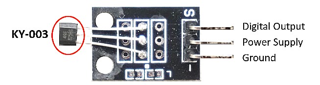
- Pin – is GND, connect to the GND of the MCU
- The middle pin is the power VCC +5v, connect to MCU +5
- Pin S signal, connect to MCU's Digital pin
Applications:
- Brushless DC electric motors to detect the position of the permanent magnet.
- Computer printers to detect missing paper and open covers.
- General switch applications
Circuit:
The Output of the module is going to be connected to the digital pin 3 on Arduino and 5v and and should be connected

Library:
Code:
We will turn on the LED on pin 13 when you put a magnet near the module.
int led = 13;//LED pin
int sensor = 3; //sensor pin
int val; //numeric variable
void setup()
{
pinMode(led, OUTPUT); //set LED pin as output
pinMode(sensor, INPUT); //set sensor pin as input
}
void loop()
{
val = digitalRead(sensor); //Read the sensor
if(val == LOW) //when magnetic field is detected, turn led on
{
digitalWrite(Led, HIGH);
}
else
{
digitalWrite(Led, LOW);
}
}
Technical Details:
| Specs | KY-003 |
| Hall-Effect Sensor | 3144EUA-S |
| Operating voltage | 4.5V...24V |
| Board dimensions | 18.5 mm x 15 mm 0.728 in x 0.591 in |
| Outputs | Digital |
| Build in resistor | - |
| Reposition | Opposite polarity of magnetic field |
Resources:
Comparisons:
The KY-003 hall sensor module is based on the 3144EUA-S hall-effect sensor and operates at a higher voltage range of 4.5V to 24V. As a result, the KY-003 module can be connected to an Arduino but not to an ESP8266 or ESP32 microcontroller board due to the low operating voltage of 3.3V. The KY-003 is smaller in size because the sensor module only outputs a digital signal. The KY-024 module is based on the SS49E hall-effect sensor, which operates between 2.7V and 6.5V. This voltage range is ideal for Arduino microcontrollers operating at 5V as well as ESP8266 and ESP32 boards operating at 3.3V. The KY-024 module is larger because it measures an analog signal and generates a digital signal, requiring additional components such as an LM393 comparator and a 100k potentiometer. The repositioning behavior is a key difference. The KY-024 returns to its initial state when the magnetic field is weak or absent, while the KY-003 requires opposite magnetic polarity for repositioning.
| Function | KY-024 | KY-003 |
| Hall-Effect Sensor | SS49E | 3144EUA-S |
| Operating voltage | 2.7V...6.5V | 4.5V...24V |
| Board dimensions | 1.5 cm x 3.6 cm 0.6 in x 1.4 in |
18.5 mm x 15 mm 0.728 in x 0.591 in |
| Outputs | Analog + Digital | Digital |
| Build in resistor | 100kΩ potentiometer | - |
| Reposition | No/weak magnetic field | Opposite polarity of magnetic field |
Features:
- Superior Temp. Stability for Automotive or Industrial Applications
- 4.5 V to 24 V Operation … Needs Only An Unregulated Supply
- Power LED Indicator
- Open-Collector 25 mA Output … Compatible with Digital Logic
- Reverse Battery Protection
- Activate with Small, Commercially Available Permanent Magnets
- Solid-State Reliability
- Small Size
- Resistant to Physical Stress
- Compatible with Arduino
Principle of Work:
When an electric current flows through a conductor, a magnetic field perpendicular to the current direction is created. This magnetic field applies a diagonal force to the moving charge carriers, pushing them to one side of the conductor. Because of the potential difference caused by the pushed outwards charge, a measurable voltage between the two sides of the conductor is produced, which is known as the Hall voltage. The Hall Effect is named after E. H. Hall, who discovered it in 1879. The effect is determined by the conductor's thickness. As a result, the conductor should be very thin.
Because of their unipolar switching characteristics, these devices are ideal for use with a simple bar or rod magnet. When the magnetic field at the Hall sensor exceeds the operating point threshold, the output of these devices (pin 3) goes low (BOP). The output voltage is VOUT at this point (SAT). The device output becomes high when the magnetic field is reduced to below the release point threshold (BRP). The difference between the magnetic operation and release points is referred to as the device's hysteresis (Bhys). This built-in hysteresis allows clean switching of the output even in the presence of external mechanical vibration and electrical noise.
Pinout of the Board:
- Pin – is GND, connect to the GND of the MCU
- The middle pin is the power VCC +5v, connect to MCU +5
- Pin S signal, connect to MCU's Digital pin
Applications:
- Brushless DC electric motors to detect the position of the permanent magnet.
- Computer printers to detect missing paper and open covers.
- General switch applications
Circuit:
The Output of the module is going to be connected to the digital pin 3 on Arduino and 5v and and should be connected
Library:
Code:
We will turn on the LED on pin 13 when you put a magnet near the module.
int led = 13;//LED pin
int sensor = 3; //sensor pin
int val; //numeric variable
void setup()
{
pinMode(led, OUTPUT); //set LED pin as output
pinMode(sensor, INPUT); //set sensor pin as input
}
void loop()
{
val = digitalRead(sensor); //Read the sensor
if(val == LOW) //when magnetic field is detected, turn led on
{
digitalWrite(Led, HIGH);
}
else
{
digitalWrite(Led, LOW);
}
}
Technical Details:
| Specs | KY-003 |
| Hall-Effect Sensor | 3144EUA-S |
| Operating voltage | 4.5V...24V |
| Board dimensions | 18.5 mm x 15 mm 0.728 in x 0.591 in |
| Outputs | Digital |
| Build in resistor | - |
| Reposition | Opposite polarity of magnetic field |
Resources:
Comparisons:
The KY-003 hall sensor module is based on the 3144EUA-S hall-effect sensor and operates at a higher voltage range of 4.5V to 24V. As a result, the KY-003 module can be connected to an Arduino but not to an ESP8266 or ESP32 microcontroller board due to the low operating voltage of 3.3V. The KY-003 is smaller in size because the sensor module only outputs a digital signal. The KY-024 module is based on the SS49E hall-effect sensor, which operates between 2.7V and 6.5V. This voltage range is ideal for Arduino microcontrollers operating at 5V as well as ESP8266 and ESP32 boards operating at 3.3V. The KY-024 module is larger because it measures an analog signal and generates a digital signal, requiring additional components such as an LM393 comparator and a 100k potentiometer. The repositioning behavior is a key difference. The KY-024 returns to its initial state when the magnetic field is weak or absent, while the KY-003 requires opposite magnetic polarity for repositioning.
| Function | KY-024 | KY-003 |
| Hall-Effect Sensor | SS49E | 3144EUA-S |
| Operating voltage | 2.7V...6.5V | 4.5V...24V |
| Board dimensions | 1.5 cm x 3.6 cm 0.6 in x 1.4 in |
18.5 mm x 15 mm 0.728 in x 0.591 in |
| Outputs | Analog + Digital | Digital |
| Build in resistor | 100kΩ potentiometer | - |
| Reposition | No/weak magnetic field | Opposite polarity of magnetic field |