Principle of Work:
- White light contains red, green, and blue components. When reflected off a surface, the sensor reads the reflected wavelengths to identify the color.
- The TCS3200 sensor uses a 4x4 array of photodiodes with red, green, blue, and clear filters arranged in a Bayer pattern.
- Each filter type corresponds to a different photodiode which converts light into current; the signal is then processed to identify RGB intensity.
- Clear filters allow more light, enhancing performance in low-light conditions.
Features:
- High-resolution light-to-frequency conversion
- Direct microcontroller communication (Arduino compatible)
- Programmable color and full-scale output frequency
- Stable temperature coefficient (200 ppm/°C)
- Upgraded version of TCS230 with improved sensitivity
- Power down feature for energy saving
- Low nonlinearity error (~0.2%)
Specifications:
- Power Supply: 3.3V or 5V
- Operating Voltage: 2.7V ~ 5.5V
- Output Frequency Voltage: 0 - 5V
- Optimal Sensing Distance: 10–15 mm
- Module Dimensions: 32 x 25 mm
- Weight: ~5g
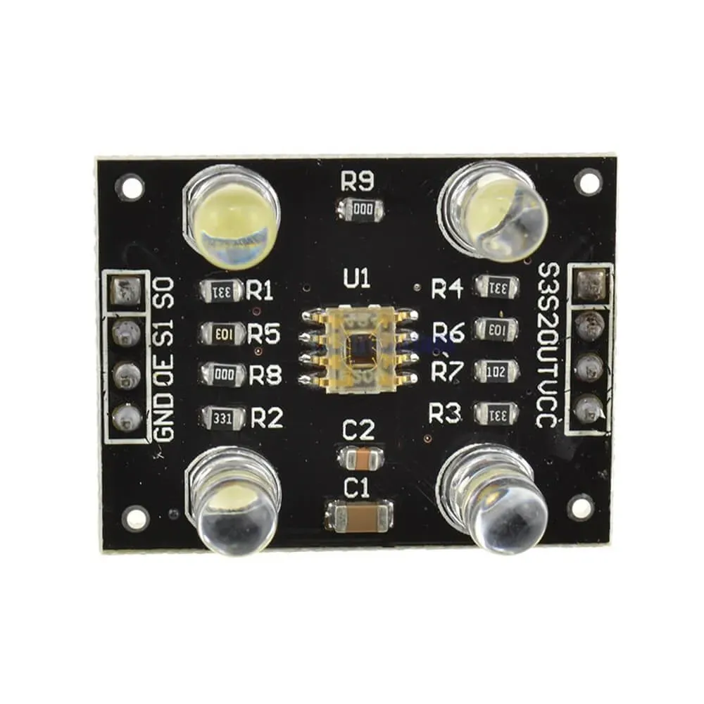
Pin Connections:
| Pin |
Description |
| S0, S1 |
Set output frequency scaling (2%, 20%, or 100%) |
| S2, S3 |
Select color filter type (Red, Green, Blue, Clear) |
| OE |
Output enable (LOW = enabled) |
| OUT |
Frequency output signal |
| VCC |
Power input (3.3V–5V) |
| GND |
Ground |
Applications:
- Color tracking in robotics
- Color sorting in manufacturing
- Lighting control systems
- Product inspection and quality control
- Interactive installations and smart lighting
- Educational demonstrations and experiments
Sample Arduino Wiring:
- S0 → Arduino D5
- S1 → Arduino D4
- S2 → Arduino D7
- S3 → Arduino D6
- OUT → Arduino D8
- VCC → 5V
- GND → GND

Sample Arduino Code:
#define S0_PIN 5
#define S1_PIN 4
#define S2_PIN 7
#define S3_PIN 6
#define OUT_PIN 8

void setup() {
  pinMode(S0_PIN, OUTPUT);
  pinMode(S1_PIN, OUTPUT);
  pinMode(S2_PIN, OUTPUT);
  pinMode(S3_PIN, OUTPUT);
  pinMode(OUT_PIN, INPUT);
  digitalWrite(S0_PIN, HIGH);
  digitalWrite(S1_PIN, LOW);
  Serial.begin(9600);
}

void loop() {
  int r = readColor(S2_PIN, S3_PIN, LOW, LOW);
  delay(200);
  int g = readColor(S2_PIN, S3_PIN, HIGH, HIGH);
  delay(200);
  int b = readColor(S2_PIN, S3_PIN, LOW, HIGH);
  delay(200);

  Serial.print("R: "); Serial.print(r);
  Serial.print(" G: "); Serial.print(g);
  Serial.print(" B: "); Serial.println(b);
}

int readColor(int s2, int s3, int s2Val, int s3Val) {
  digitalWrite(s2, s2Val);
  digitalWrite(s3, s3Val);
  return pulseIn(OUT_PIN, LOW);
}
Troubleshooting Tips:
- Ensure correct voltage supply (2.7V to 5.5V)
- Avoid ambient light interference by using a cover
- Verify pin configurations for S0–S3
References:
Principle of Work:
- White light contains red, green, and blue components. When reflected off a surface, the sensor reads the reflected wavelengths to identify the color.
- The TCS3200 sensor uses a 4x4 array of photodiodes with red, green, blue, and clear filters arranged in a Bayer pattern.
- Each filter type corresponds to a different photodiode which converts light into current; the signal is then processed to identify RGB intensity.
- Clear filters allow more light, enhancing performance in low-light conditions.
Features:
- High-resolution light-to-frequency conversion
- Direct microcontroller communication (Arduino compatible)
- Programmable color and full-scale output frequency
- Stable temperature coefficient (200 ppm/°C)
- Upgraded version of TCS230 with improved sensitivity
- Power down feature for energy saving
- Low nonlinearity error (~0.2%)
Specifications:
- Power Supply: 3.3V or 5V
- Operating Voltage: 2.7V ~ 5.5V
- Output Frequency Voltage: 0 - 5V
- Optimal Sensing Distance: 10–15 mm
- Module Dimensions: 32 x 25 mm
- Weight: ~5g
Pin Connections:
| Pin |
Description |
| S0, S1 |
Set output frequency scaling (2%, 20%, or 100%) |
| S2, S3 |
Select color filter type (Red, Green, Blue, Clear) |
| OE |
Output enable (LOW = enabled) |
| OUT |
Frequency output signal |
| VCC |
Power input (3.3V–5V) |
| GND |
Ground |
Applications:
- Color tracking in robotics
- Color sorting in manufacturing
- Lighting control systems
- Product inspection and quality control
- Interactive installations and smart lighting
- Educational demonstrations and experiments
Sample Arduino Wiring:
- S0 → Arduino D5
- S1 → Arduino D4
- S2 → Arduino D7
- S3 → Arduino D6
- OUT → Arduino D8
- VCC → 5V
- GND → GND
Sample Arduino Code:
#define S0_PIN 5
#define S1_PIN 4
#define S2_PIN 7
#define S3_PIN 6
#define OUT_PIN 8

void setup() {
  pinMode(S0_PIN, OUTPUT);
  pinMode(S1_PIN, OUTPUT);
  pinMode(S2_PIN, OUTPUT);
  pinMode(S3_PIN, OUTPUT);
  pinMode(OUT_PIN, INPUT);
  digitalWrite(S0_PIN, HIGH);
  digitalWrite(S1_PIN, LOW);
  Serial.begin(9600);
}

void loop() {
  int r = readColor(S2_PIN, S3_PIN, LOW, LOW);
  delay(200);
  int g = readColor(S2_PIN, S3_PIN, HIGH, HIGH);
  delay(200);
  int b = readColor(S2_PIN, S3_PIN, LOW, HIGH);
  delay(200);

  Serial.print("R: "); Serial.print(r);
  Serial.print(" G: "); Serial.print(g);
  Serial.print(" B: "); Serial.println(b);
}

int readColor(int s2, int s3, int s2Val, int s3Val) {
  digitalWrite(s2, s2Val);
  digitalWrite(s3, s3Val);
  return pulseIn(OUT_PIN, LOW);
}
Troubleshooting Tips:
- Ensure correct voltage supply (2.7V to 5.5V)
- Avoid ambient light interference by using a cover
- Verify pin configurations for S0–S3
References: