
Features
- Integrated MAX7219 LED driver for direct microcontroller control
- Supports 8 x 8 LED matrices, 7-segment displays, and bar graph displays
- B-type BCD encoder and multi-channel scan loop integrated on-chip
- Onboard RAM for storing display data
- Four-wire serial interface using minimal I/O pins
- Adjustable brightness via software control
- Low-power shutdown mode
- Supports cascading multiple modules
- Compact PCB with mounting holes for secure installation
Specifications
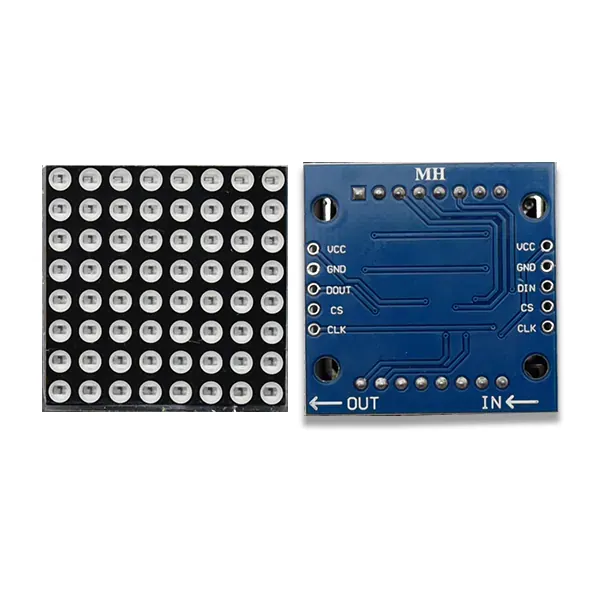
- Driver IC: MAX7219
- Display Type: 8 x 8 common cathode LED matrix
- Operating Voltage: 5V DC
- Interface: Serial (DIN, CS, CLK)
- Cascade Support: Yes
- Module Dimensions: 3.2 cm x 3.2 cm x 1.3 cm
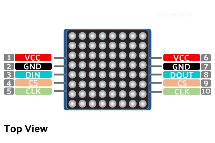
Pinout
| Pin | Description |
|---|---|
| VCC | Power supply pin, connect to +5V |
| GND | Ground pin |
| DIN | Serial data input |
| CS | Chip select pin |
| CLK | Serial clock pin |
Arduino Library
For easy control of the MAX7219 module with Arduino, it is recommended to use the LedControl library.
- Open Arduino IDE
- Go to Sketch > Include Library > Manage Libraries
- Search for LedControl
- Install the library by Eberhard Fahle
Arduino Example Code
// MAX7219 LED Matrix Arduino Example
#include <LedControl.h>

// Pin configuration
#define DIN_PIN 12
#define CLK_PIN 11
#define CS_PIN 10

// Create LedControl object
LedControl lc = LedControl(DIN_PIN, CLK_PIN, CS_PIN, 1);

void setup() {
  lc.shutdown(0, false);      // Wake up the MAX7219
  lc.setIntensity(0, 8);      // Set brightness (0-15)
  lc.clearDisplay(0);         // Clear display
}

void loop() {
  // Display a simple pattern
  byte smiley[8] = {
    B00111100,
    B01000010,
    B10100101,
    B10000001,
    B10100101,
    B10011001,
    B01000010,
    B00111100
  };

  for (int row = 0; row < 8; row++) {
    lc.setRow(0, row, smiley[row]);
  }

  delay(2000);
  lc.clearDisplay(0);
  delay(1000);
}
Applications
- Scrolling text and message displays
- Digital clocks and counters
- Status indicators and dashboards
- Educational electronics projects
- DIY and hobbyist LED display systems
Features
- Integrated MAX7219 LED driver for direct microcontroller control
- Supports 8 x 8 LED matrices, 7-segment displays, and bar graph displays
- B-type BCD encoder and multi-channel scan loop integrated on-chip
- Onboard RAM for storing display data
- Four-wire serial interface using minimal I/O pins
- Adjustable brightness via software control
- Low-power shutdown mode
- Supports cascading multiple modules
- Compact PCB with mounting holes for secure installation
Specifications
- Driver IC: MAX7219
- Display Type: 8 x 8 common cathode LED matrix
- Operating Voltage: 5V DC
- Interface: Serial (DIN, CS, CLK)
- Cascade Support: Yes
- Module Dimensions: 3.2 cm x 3.2 cm x 1.3 cm
Pinout
| Pin | Description |
|---|---|
| VCC | Power supply pin, connect to +5V |
| GND | Ground pin |
| DIN | Serial data input |
| CS | Chip select pin |
| CLK | Serial clock pin |
Arduino Library
For easy control of the MAX7219 module with Arduino, it is recommended to use the LedControl library.
- Open Arduino IDE
- Go to Sketch > Include Library > Manage Libraries
- Search for LedControl
- Install the library by Eberhard Fahle
Arduino Example Code
// MAX7219 LED Matrix Arduino Example
#include <LedControl.h>

// Pin configuration
#define DIN_PIN 12
#define CLK_PIN 11
#define CS_PIN 10

// Create LedControl object
LedControl lc = LedControl(DIN_PIN, CLK_PIN, CS_PIN, 1);

void setup() {
  lc.shutdown(0, false);      // Wake up the MAX7219
  lc.setIntensity(0, 8);      // Set brightness (0-15)
  lc.clearDisplay(0);         // Clear display
}

void loop() {
  // Display a simple pattern
  byte smiley[8] = {
    B00111100,
    B01000010,
    B10100101,
    B10000001,
    B10100101,
    B10011001,
    B01000010,
    B00111100
  };

  for (int row = 0; row < 8; row++) {
    lc.setRow(0, row, smiley[row]);
  }

  delay(2000);
  lc.clearDisplay(0);
  delay(1000);
}
Applications
- Scrolling text and message displays
- Digital clocks and counters
- Status indicators and dashboards
- Educational electronics projects
- DIY and hobbyist LED display systems