
The module communicates through a two-wire I2C interface with data output rates of up to 80 Hz and supports fast-mode I2C operation up to 400 kHz. It operates from a low-voltage power supply ranging between 1.95 V and 3.6 V. Standard 2.54 mm pin spacing makes it easy to use on breadboards, and the board includes selectable I2C pull-up resistors via solder jumpers along with multiple mounting holes.
Features
- Digital triple-axis magnetic field sensing
- Onboard ASIC for control and I2C communication
- Orientation-independent compass capability when paired with an accelerometer
- Fast-mode I2C interface up to 400 kHz
- Selectable I2C pull-up resistors via solder jumpers
- Integrated temperature sensor
- Standard 2.54 mm pin spacing for easy breadboarding
- Four mounting holes for secure installation
Specifications
- Operating voltage: 1.95 V to 3.6 V
- Full-scale magnetic field range: ±1000 uT
- Sensitivity: 0.10 uT
- Interface: I2C (up to 400 kHz fast mode)
- Maximum output data rate: 80 Hz
- I2C pull-ups: Selectable via solder jumpers
- Integrated temperature sensor
- Mounting holes: 4
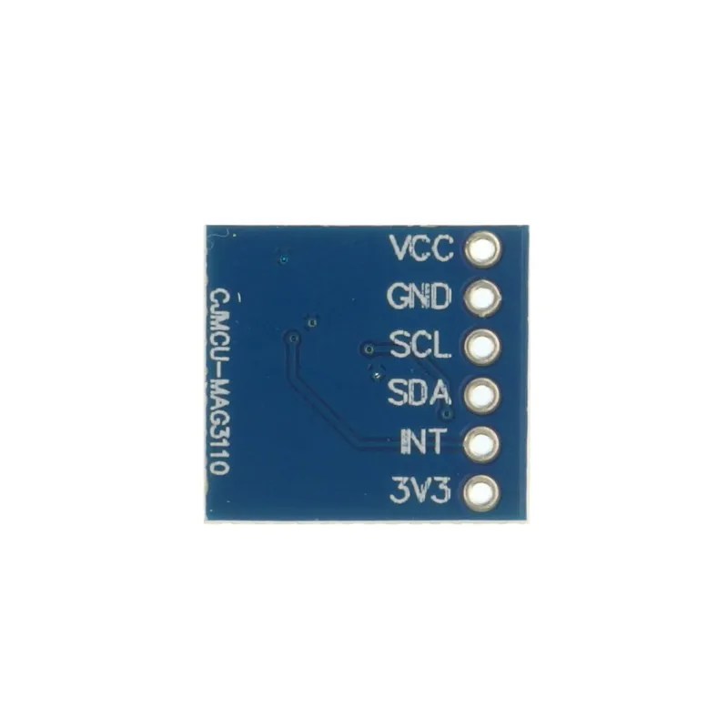
Pinout
| Pin | Description |
|---|---|
| 3.3V | Supply voltage (3.3V) |
| GND | Ground connection |
| SDA | Serial data line for I2C communication |
| SCL | Serial clock line for I2C communication |
| INT | Interrupt output, goes high when new data is ready |
| VCC | Supply voltage (5V input via onboard regulation) |
Applications
- Electronic compass systems
- UAV and robotics navigation
- Dead-reckoning systems
How to Use
- Power the module using either the 3.3V pin or the VCC pin (if onboard regulation is available).
- Connect the module to a microcontroller using the I2C interface.
- Ensure the I2C pull-up resistors are enabled if required (via onboard solder jumpers).
- Upload the example code to initialize the sensor and read magnetic field data.
- Place the module away from strong magnetic fields such as motors, speakers, or metal objects.
- Use the X, Y, and Z magnetic data to determine heading or orientation.
Typical Connections (Arduino Uno)
| Module Pin | Arduino Uno |
|---|---|
| 3.3V | 3.3V |
| GND | GND |
| SDA | A4 |
| SCL | A5 |
| INT | Not Connected (Optional) |
Library Requirement
- Install the Adafruit MAG3110 library from the Arduino Library Manager.
- Also install the Adafruit Unified Sensor library if prompted.
Example Code (Arduino)
#include "Wire.h"
#include "Adafruit_Sensor.h"
#include "Adafruit_MAG3110.h"

Adafruit_MAG3110 mag = Adafruit_MAG3110();

void setup() {
  Serial.begin(9600);
  Wire.begin();

  if (!mag.begin()) {
    Serial.println("MAG3110 not detected!");
    while (1);
  }
}

void loop() {
  mag.read();

  Serial.print("X: ");
  Serial.print(mag.x);
  Serial.print("  Y: ");
  Serial.print(mag.y);
  Serial.print("  Z: ");
  Serial.println(mag.z);

  delay(500);
}
Code Explanation
- Initializes I2C communication and the magnetic sensor.
- Reads magnetic field values along X, Y, and Z axes.
- Outputs raw magnetic field data to the Serial Monitor.
- Data can be processed further to calculate compass heading.
Applications
- Electronic compass and heading systems
- Robotics navigation and orientation
- UAV flight stabilization
- Dead-reckoning and motion tracking systems
The module communicates through a two-wire I2C interface with data output rates of up to 80 Hz and supports fast-mode I2C operation up to 400 kHz. It operates from a low-voltage power supply ranging between 1.95 V and 3.6 V. Standard 2.54 mm pin spacing makes it easy to use on breadboards, and the board includes selectable I2C pull-up resistors via solder jumpers along with multiple mounting holes.
Features
- Digital triple-axis magnetic field sensing
- Onboard ASIC for control and I2C communication
- Orientation-independent compass capability when paired with an accelerometer
- Fast-mode I2C interface up to 400 kHz
- Selectable I2C pull-up resistors via solder jumpers
- Integrated temperature sensor
- Standard 2.54 mm pin spacing for easy breadboarding
- Four mounting holes for secure installation
Specifications
- Operating voltage: 1.95 V to 3.6 V
- Full-scale magnetic field range: ±1000 uT
- Sensitivity: 0.10 uT
- Interface: I2C (up to 400 kHz fast mode)
- Maximum output data rate: 80 Hz
- I2C pull-ups: Selectable via solder jumpers
- Integrated temperature sensor
- Mounting holes: 4
Pinout
| Pin | Description |
|---|---|
| 3.3V | Supply voltage (3.3V) |
| GND | Ground connection |
| SDA | Serial data line for I2C communication |
| SCL | Serial clock line for I2C communication |
| INT | Interrupt output, goes high when new data is ready |
| VCC | Supply voltage (5V input via onboard regulation) |
Applications
- Electronic compass systems
- UAV and robotics navigation
- Dead-reckoning systems
How to Use
- Power the module using either the 3.3V pin or the VCC pin (if onboard regulation is available).
- Connect the module to a microcontroller using the I2C interface.
- Ensure the I2C pull-up resistors are enabled if required (via onboard solder jumpers).
- Upload the example code to initialize the sensor and read magnetic field data.
- Place the module away from strong magnetic fields such as motors, speakers, or metal objects.
- Use the X, Y, and Z magnetic data to determine heading or orientation.
Typical Connections (Arduino Uno)
| Module Pin | Arduino Uno |
|---|---|
| 3.3V | 3.3V |
| GND | GND |
| SDA | A4 |
| SCL | A5 |
| INT | Not Connected (Optional) |
Library Requirement
- Install the Adafruit MAG3110 library from the Arduino Library Manager.
- Also install the Adafruit Unified Sensor library if prompted.
Example Code (Arduino)
#include "Wire.h"
#include "Adafruit_Sensor.h"
#include "Adafruit_MAG3110.h"

Adafruit_MAG3110 mag = Adafruit_MAG3110();

void setup() {
  Serial.begin(9600);
  Wire.begin();

  if (!mag.begin()) {
    Serial.println("MAG3110 not detected!");
    while (1);
  }
}

void loop() {
  mag.read();

  Serial.print("X: ");
  Serial.print(mag.x);
  Serial.print("  Y: ");
  Serial.print(mag.y);
  Serial.print("  Z: ");
  Serial.println(mag.z);

  delay(500);
}
Code Explanation
- Initializes I2C communication and the magnetic sensor.
- Reads magnetic field values along X, Y, and Z axes.
- Outputs raw magnetic field data to the Serial Monitor.
- Data can be processed further to calculate compass heading.
Applications
- Electronic compass and heading systems
- Robotics navigation and orientation
- UAV flight stabilization
- Dead-reckoning and motion tracking systems