
Features
- Biometric pulse and heart rate detection sensor
- Can be attached to finger or earlobe for accurate readings
- Plug-and-play design with simple 3-pin interface
- Built-in signal amplification and noise cancellation circuitry
- Low power consumption suitable for portable and wearable devices
- Compatible with a wide range of development boards
- Ideal for medical, fitness, and research projects
Specifications
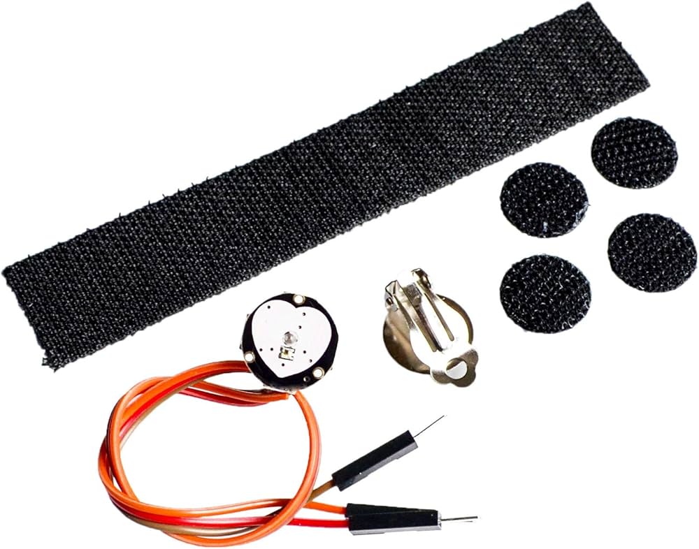
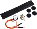
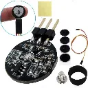
- Sensor Diameter: 0.625 inch (≈16 mm)
- Overall Thickness: 0.125 inch (≈3 mm)
- Working Voltage: 3V to 5V
- Working Current: ~4 mA at 5V
- Output Type: Analog pulsating signal
- Integrated Circuits: Amplification and noise cancellation
Principle of Work:
The Pulse Sensor works on the principle of Photoplethysmography (PPG), which is a non-invasive method for measuring changes in blood volume under the skin. The sensor essentially consists of two main components: a light-emitting diode (LED) that shines light into the skin and a photodetector that measures the amount of light that is reflected back. Here’s a detailed explanation of its working:

- Light Emission: A green LED emits light into the skin.
- Reflection & Detection: The light interacts with blood and is partially reflected back, captured by a photodetector.
- Heart Rate: Changes in reflected light create a waveform that correlates with heartbeats.
- Oxygen Level: The amount of reflected light also indicates blood oxygen levels, as oxygenated blood absorbs more green light.
- Signal Filtering: A Low Pass Filter cleans up the noisy, raw signal from the photodetector.
- Amplification: An operational amplifier boosts the filtered signal for better accuracy.
- Data Reading: Finally, an Arduino reads the amplified signal and software algorithms translate it into heart rate and potentially blood oxygen levels.
Pinout of the Module

| Pin Number | Pin Name | Wire Colour | Description |
|---|---|---|---|
| 1 | Ground | Black | Connected to the ground of the system |
| 2 | VCC | Red | Connect to +3.3V or +5V supply voltage |
| 3 | Signal | Purple | Pulsating analog output signal |
Supported Development Boards
- STM32 full range of chips and development boards (MDK, IAR)
- Arduino series (UNO R3, Mega 2560, Leonardo, etc.)
- 8051 series development boards (STC12C5A60S2)
- MSP430 series (LaunchPad G2, MSP430FR5969)
- KL25Z development board (MKL25Z128VLK4 ARM Cortex-M0+)
Applications
- Sleep tracking systems
- Anxiety and stress monitoring
- Remote patient monitoring and alarm systems
- Health bands and wearable devices
- Advanced gaming and interactive consoles
Getting Started Tutorial
A step-by-step getting started tutorial is available to help you quickly connect the sensor and begin measuring heart rate data with your preferred development board: Link
Features
- Biometric pulse and heart rate detection sensor
- Can be attached to finger or earlobe for accurate readings
- Plug-and-play design with simple 3-pin interface
- Built-in signal amplification and noise cancellation circuitry
- Low power consumption suitable for portable and wearable devices
- Compatible with a wide range of development boards
- Ideal for medical, fitness, and research projects
Specifications
- Sensor Diameter: 0.625 inch (≈16 mm)
- Overall Thickness: 0.125 inch (≈3 mm)
- Working Voltage: 3V to 5V
- Working Current: ~4 mA at 5V
- Output Type: Analog pulsating signal
- Integrated Circuits: Amplification and noise cancellation
Principle of Work:
The Pulse Sensor works on the principle of Photoplethysmography (PPG), which is a non-invasive method for measuring changes in blood volume under the skin. The sensor essentially consists of two main components: a light-emitting diode (LED) that shines light into the skin and a photodetector that measures the amount of light that is reflected back. Here’s a detailed explanation of its working:
- Light Emission: A green LED emits light into the skin.
- Reflection & Detection: The light interacts with blood and is partially reflected back, captured by a photodetector.
- Heart Rate: Changes in reflected light create a waveform that correlates with heartbeats.
- Oxygen Level: The amount of reflected light also indicates blood oxygen levels, as oxygenated blood absorbs more green light.
- Signal Filtering: A Low Pass Filter cleans up the noisy, raw signal from the photodetector.
- Amplification: An operational amplifier boosts the filtered signal for better accuracy.
- Data Reading: Finally, an Arduino reads the amplified signal and software algorithms translate it into heart rate and potentially blood oxygen levels.
Pinout of the Module
| Pin Number | Pin Name | Wire Colour | Description |
|---|---|---|---|
| 1 | Ground | Black | Connected to the ground of the system |
| 2 | VCC | Red | Connect to +3.3V or +5V supply voltage |
| 3 | Signal | Purple | Pulsating analog output signal |
Supported Development Boards
- STM32 full range of chips and development boards (MDK, IAR)
- Arduino series (UNO R3, Mega 2560, Leonardo, etc.)
- 8051 series development boards (STC12C5A60S2)
- MSP430 series (LaunchPad G2, MSP430FR5969)
- KL25Z development board (MKL25Z128VLK4 ARM Cortex-M0+)
Applications
- Sleep tracking systems
- Anxiety and stress monitoring
- Remote patient monitoring and alarm systems
- Health bands and wearable devices
- Advanced gaming and interactive consoles
Getting Started Tutorial
A step-by-step getting started tutorial is available to help you quickly connect the sensor and begin measuring heart rate data with your preferred development board: Link