Features:
- High-resolution Photosensitive Array: 640 x 480 pixels for detailed images and videos.
- Low Operating Voltage: Works at 2.5V to 3.0V.
- Efficient Power Consumption: 60mW at 15fps (VGAYUV).
- Energy-saving Sleeping Mode: Consumes less than 20uA.
- Wide Operating Temperature Range: -30 to 70°C.
- Versatile Output Formats: YUV/YCbCr4:2:2, RGB565/555/444, GRB4:2:2, Raw RGB.
- Compact Lens Size & Wide Vision Angle: 1/6" lens, 25° field of view.
- High Frame Rate: Up to 30fps VGA.
- Low Light Sensitivity: 1.3V/(Lux-sec).
- Excellent Signal-to-Noise Ratio: 46 dB.
- Dynamic Range: 52 dB.
- Electronic Exposure Control for optimal imaging.
- Low Dark Current: 12 mV/s at 6°C.
Description:
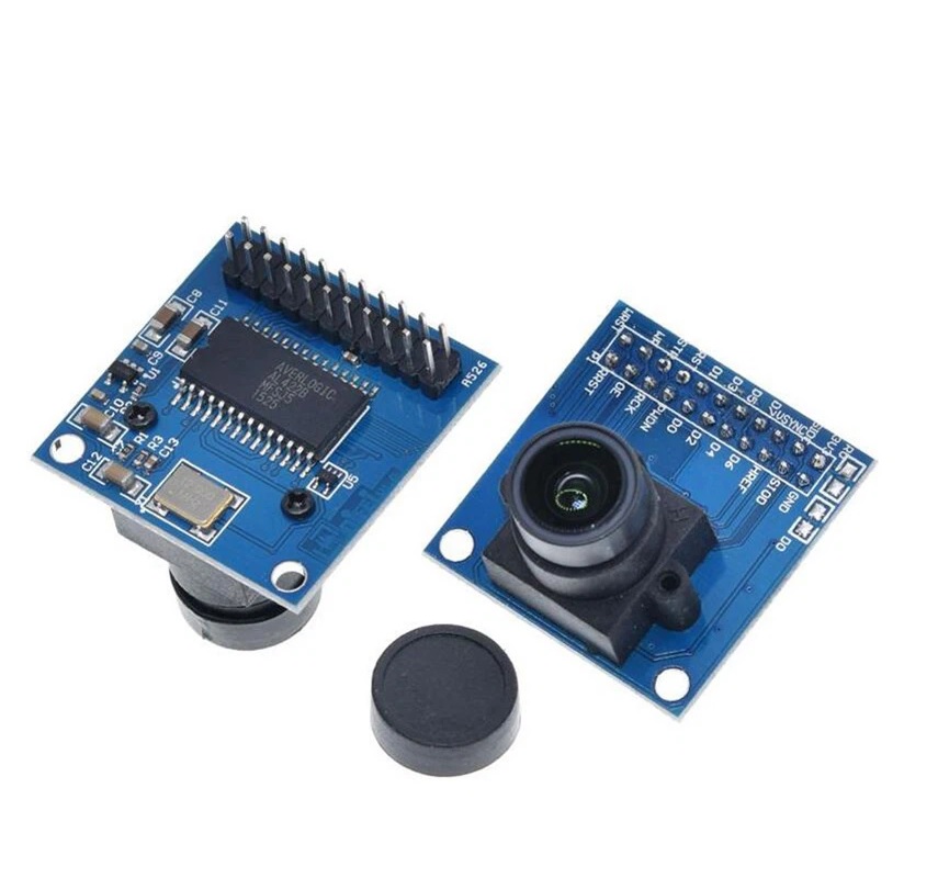
The OV7670 camera module is designed for seamless integration with microcontrollers such as Arduino, making it perfect for surveillance systems and real-time monitoring. Whether you're keeping an eye on a construction site or checking the progress of a 3D printer, this module provides real-time capture in a compact, flexible form factor.
The onboard FIFO buffer ensures smooth data transfer, allowing the microcontroller to read image data without missing frames. Using CMOS technology, the module offers low power consumption and high-quality image capture. Its 640x480 resolution delivers clear results suitable for video streaming, interactive displays, and computer vision experiments.
Principle of Work:
- Photosensitive Array: Captures light using tiny pixels that convert light into electrical signals.
- ADC: Converts analog signals from the pixels into digital data.
- Signal Processing: Handles noise reduction, color correction, exposure, and white balance.
- Output Interface: Sends the processed image data through parallel or serial lines.
How It Works with Arduino (MCU):
- Connection: Camera pins connect to Arduino data, control, and power pins.
- Initialization: Arduino configures resolution, exposure, color format.
- Image Capture: Arduino triggers camera to start frame capture.
- Data Transfer: Camera sends pixel data via parallel lines to Arduino memory.
- Image Processing: Arduino may run filters, detection algorithms, or compression.
- Output/Display: Data can be streamed, saved, or displayed.
Pinout of the Module:
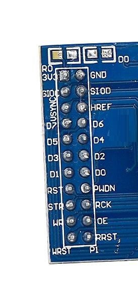
- VCC: 3.3V
- GND: Ground
- SIOC: Clock (SCCB/I2C)
- SIOD: Data (SCCB/I2C)
- VSYNC: Vertical sync
- HREF: Horizontal reference
- D7–D0: Data output lines
- RST: Reset
- PWDN: Power-down
- STR: Strobe
- RCK: Read clock
- WR: Write clock
- OE: Output enable
- WRST: Write reset
- P1: Configurable pin
Applications:
- Surveillance systems
- Robotics & drones for navigation and object tracking
- Image processing & computer vision
- Remote monitoring of 3D printers
- Video streaming and recording
- Interactive displays & AR setups
- Educational embedded systems projects
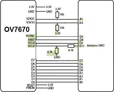
Circuit:
Library Installation:
- Open Arduino IDE.
- Go to Sketch → Include Library → Manage Libraries.
- Search for “OV7670”.
- Install the library.
- Restart the IDE if needed.
Code:
#include "Wire.h"
#include "OV7670.h"

OV7670 camera;

void setup() {
  Serial.begin(9600);
  camera.begin();

  #ifdef useVga
    camera.setResolution(VGA);
    camera.setColorSpace(BAYER_RGB);
    camera.writeRegister(0x11, 25);
  #elif defined(useQvga)
    camera.setResolution(QVGA);
    camera.setColorSpace(YUV422);
    camera.writeRegister(0x11, 12);
  #else
    camera.setResolution(QQVGA);
    camera.setColorSpace(YUV422);
    camera.writeRegister(0x11, 3);
  #endif
}

void loop() {
  captureImage();
  delay(1000);
}

void captureImage() {
  Serial.println("RDY");

  while (!digitalRead(3));
  while (digitalRead(3));

  #ifdef useVga
    camera.captureFrame(640, 480);
  #elif defined(useQvga)
    camera.captureFrame(320, 240);
  #else
    camera.captureFrame(160, 120);
  #endif
}
Technical Details:
- Lens Size: 1/6"
- Field of View: 25°
- Pixel Size: 3.6um x 3.6um
- SNR: 46 dB
- Output Formats: YUV/YCbCr, RGB565/555/444, GRB4:2:2, Raw RGB
- Voltage: 2.5V–3.0V
- Max Frame Rate: 30fps VGA
- Dynamic Range: 52 dB
- Power: 60mW
- Sleep Mode: <20uA
- Operating Temperature: -30 to 70°C
- Photosensitive Array: 640x480
- Sensitivity: 1.3V/(Lux-sec)
- Electronic Exposure: 1–510 rows
- Dark Current: 12 mV/s at 6°C
Resources:
- embeddedprogrammer.blogspot.com.es/2012/07/hacking-ov7670-camera-module-sccb-cheat.html
- web.archive.org/.../nicolasfley.fast-page.org
- rpg.fi/desaster/blog/
Comparison: With FIFO vs Without FIFO
With FIFO:
- Has internal buffer for frame storage.
- Smooth, uninterrupted data readout.
- Less data loss.
- Easier for slower microcontrollers.
Without FIFO:
- No internal frame buffer.
- MCU must read pixel data in real time.
- Simpler hardware, cheaper module.
- Harder for slower or busy microcontrollers.
Features:
- High-resolution Photosensitive Array: 640 x 480 pixels for detailed images and videos.
- Low Operating Voltage: Works at 2.5V to 3.0V.
- Efficient Power Consumption: 60mW at 15fps (VGAYUV).
- Energy-saving Sleeping Mode: Consumes less than 20uA.
- Wide Operating Temperature Range: -30 to 70°C.
- Versatile Output Formats: YUV/YCbCr4:2:2, RGB565/555/444, GRB4:2:2, Raw RGB.
- Compact Lens Size & Wide Vision Angle: 1/6" lens, 25° field of view.
- High Frame Rate: Up to 30fps VGA.
- Low Light Sensitivity: 1.3V/(Lux-sec).
- Excellent Signal-to-Noise Ratio: 46 dB.
- Dynamic Range: 52 dB.
- Electronic Exposure Control for optimal imaging.
- Low Dark Current: 12 mV/s at 6°C.
Description:
The OV7670 camera module is designed for seamless integration with microcontrollers such as Arduino, making it perfect for surveillance systems and real-time monitoring. Whether you're keeping an eye on a construction site or checking the progress of a 3D printer, this module provides real-time capture in a compact, flexible form factor.
The onboard FIFO buffer ensures smooth data transfer, allowing the microcontroller to read image data without missing frames. Using CMOS technology, the module offers low power consumption and high-quality image capture. Its 640x480 resolution delivers clear results suitable for video streaming, interactive displays, and computer vision experiments.
Principle of Work:
- Photosensitive Array: Captures light using tiny pixels that convert light into electrical signals.
- ADC: Converts analog signals from the pixels into digital data.
- Signal Processing: Handles noise reduction, color correction, exposure, and white balance.
- Output Interface: Sends the processed image data through parallel or serial lines.
How It Works with Arduino (MCU):
- Connection: Camera pins connect to Arduino data, control, and power pins.
- Initialization: Arduino configures resolution, exposure, color format.
- Image Capture: Arduino triggers camera to start frame capture.
- Data Transfer: Camera sends pixel data via parallel lines to Arduino memory.
- Image Processing: Arduino may run filters, detection algorithms, or compression.
- Output/Display: Data can be streamed, saved, or displayed.
Pinout of the Module:
- VCC: 3.3V
- GND: Ground
- SIOC: Clock (SCCB/I2C)
- SIOD: Data (SCCB/I2C)
- VSYNC: Vertical sync
- HREF: Horizontal reference
- D7–D0: Data output lines
- RST: Reset
- PWDN: Power-down
- STR: Strobe
- RCK: Read clock
- WR: Write clock
- OE: Output enable
- WRST: Write reset
- P1: Configurable pin
Applications:
- Surveillance systems
- Robotics & drones for navigation and object tracking
- Image processing & computer vision
- Remote monitoring of 3D printers
- Video streaming and recording
- Interactive displays & AR setups
- Educational embedded systems projects
Circuit:
Library Installation:
- Open Arduino IDE.
- Go to Sketch → Include Library → Manage Libraries.
- Search for “OV7670”.
- Install the library.
- Restart the IDE if needed.
Code:
#include "Wire.h"
#include "OV7670.h"

OV7670 camera;

void setup() {
  Serial.begin(9600);
  camera.begin();

  #ifdef useVga
    camera.setResolution(VGA);
    camera.setColorSpace(BAYER_RGB);
    camera.writeRegister(0x11, 25);
  #elif defined(useQvga)
    camera.setResolution(QVGA);
    camera.setColorSpace(YUV422);
    camera.writeRegister(0x11, 12);
  #else
    camera.setResolution(QQVGA);
    camera.setColorSpace(YUV422);
    camera.writeRegister(0x11, 3);
  #endif
}

void loop() {
  captureImage();
  delay(1000);
}

void captureImage() {
  Serial.println("RDY");

  while (!digitalRead(3));
  while (digitalRead(3));

  #ifdef useVga
    camera.captureFrame(640, 480);
  #elif defined(useQvga)
    camera.captureFrame(320, 240);
  #else
    camera.captureFrame(160, 120);
  #endif
}
Technical Details:
- Lens Size: 1/6"
- Field of View: 25°
- Pixel Size: 3.6um x 3.6um
- SNR: 46 dB
- Output Formats: YUV/YCbCr, RGB565/555/444, GRB4:2:2, Raw RGB
- Voltage: 2.5V–3.0V
- Max Frame Rate: 30fps VGA
- Dynamic Range: 52 dB
- Power: 60mW
- Sleep Mode: <20uA
- Operating Temperature: -30 to 70°C
- Photosensitive Array: 640x480
- Sensitivity: 1.3V/(Lux-sec)
- Electronic Exposure: 1–510 rows
- Dark Current: 12 mV/s at 6°C
Resources:
- embeddedprogrammer.blogspot.com.es/2012/07/hacking-ov7670-camera-module-sccb-cheat.html
- web.archive.org/.../nicolasfley.fast-page.org
- rpg.fi/desaster/blog/
Comparison: With FIFO vs Without FIFO
With FIFO:
- Has internal buffer for frame storage.
- Smooth, uninterrupted data readout.
- Less data loss.
- Easier for slower microcontrollers.
Without FIFO:
- No internal frame buffer.
- MCU must read pixel data in real time.
- Simpler hardware, cheaper module.
- Harder for slower or busy microcontrollers.