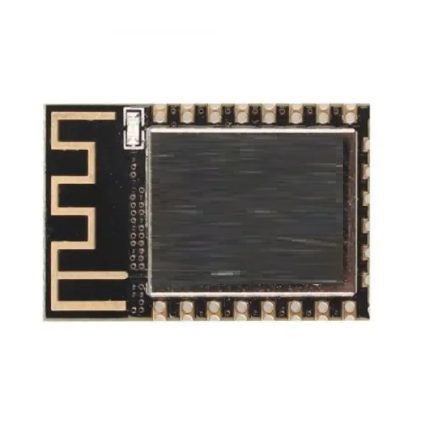
ESP8266 ESP-12F WiFi Module 4M
The high-performance chip ESP8266EX powers the ESP-12F module. It features a sophisticated Tensilica L106 32-bit MCU with 16-bit short mode, supporting frequencies of 80MHz and 160MHz along with RTOS support. The chip has complete WiFi functionality and can be used independently or as a slave device with another MCU via SPI, SDIO, I2C, or UART interfaces.
It comes with a built-in high-speed buffer for improved performance and can boot directly from onboard flash. The ESP8266EX enables low-power consumption, fast wake-up, and reliable wireless communication in compact embedded applications.
Package Includes:
- 1 x ESP-12F WiFi Module (ESP8266EX)
Specifications:
- Built-in Tensilica L106 ultra-low-power 32-bit CPU
- Main frequency: 80MHz / 160MHz with RTOS support
- Built-in TCP/IP protocol stack
- 10-bit high-precision ADC (1 channel)
- Peripheral Interfaces: HSPI, UART, I2C, I2S, IR Remote Control, PWM, GPIO
- Deep sleep current: 10µA; Cut-off current: < 5µA
- Wake, connect, and transmit in under 2ms
- Power consumption < 1.0mW in standby (DTIM3)
- Built-in 1MB SPI Flash
- Working temperature: -40℃ to +125℃
- Module size: 16mm × 24mm
WiFi Properties:
- Supports IEEE 802.11 b/g/n/e/i
- WiFi Modes: Station, Soft AP, Soft AP + STA
- Supports WiFi Direct (P2P)
- Supports WPA/WPA2 PSK, WPS, and 802.11 security certification
- Encryption: CCMP, TKIP, WEP, WAPI, CRC (hardware accelerated)
- P2P: Discovery, GO/GC mode, power management
- Supports 802.11n (2.4GHz)
- 802.1h/RFC1042 encapsulation
- Supports OTA (Over-the-Air) and AN cloud updates
- Supports Smart Config (Android and iOS compatible)
Module Interface:
- 2 x UART
- 1 x ADC
- 1 x EN
- 1 x Wake-Up Pin
- 1 x HSPI
- 1 x I2C
- 1 x I2S
- 10+ GPIOs
Programming with USB to Serial Converter:
To program the ESP-12F module using a USB to Serial converter (e.g., CH340 or PL2303), ensure the following:
- Use 3.3V logic level and power — do not use 5V
- Use a 3.3V power supply capable of supplying ~250mA
- Recommended: Add a decoupling capacitor between VCC and GND
Basic Programming Circuit:
- EN, RST, and GPIO0 → Pull HIGH via 10kΩ resistors
- GPIO15 → Pull LOW via 10kΩ resistor
- Power the module with a 3.3V regulated supply
With this configuration, the ESP8266 will power on in normal operation mode and run uploaded sketches.
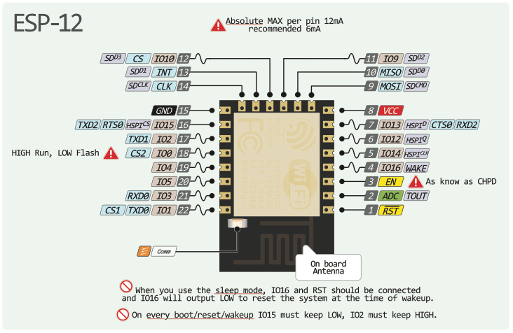
Pinout of the Module:
References:
Specifications:
- Built-in Tensilica L106 ultra-low-power 32-bit CPU
- Main frequency: 80MHz / 160MHz with RTOS support
- Built-in TCP/IP protocol stack
- 10-bit high-precision ADC (1 channel)
- Peripheral Interfaces: HSPI, UART, I2C, I2S, IR Remote Control, PWM, GPIO
- Deep sleep current: 10µA; Cut-off current: < 5µA
- Wake, connect, and transmit in under 2ms
- Power consumption < 1.0mW in standby (DTIM3)
- Built-in 1MB SPI Flash
- Working temperature: -40℃ to +125℃
- Module size: 16mm × 24mm
WiFi Properties:
- Supports IEEE 802.11 b/g/n/e/i
- WiFi Modes: Station, Soft AP, Soft AP + STA
- Supports WiFi Direct (P2P)
- Supports WPA/WPA2 PSK, WPS, and 802.11 security certification
- Encryption: CCMP, TKIP, WEP, WAPI, CRC (hardware accelerated)
- P2P: Discovery, GO/GC mode, power management
- Supports 802.11n (2.4GHz)
- 802.1h/RFC1042 encapsulation
- Supports OTA (Over-the-Air) and AN cloud updates
- Supports Smart Config (Android and iOS compatible)
Module Interface:
- 2 x UART
- 1 x ADC
- 1 x EN
- 1 x Wake-Up Pin
- 1 x HSPI
- 1 x I2C
- 1 x I2S
- 10+ GPIOs
Programming with USB to Serial Converter:
To program the ESP-12F module using a USB to Serial converter (e.g., CH340 or PL2303), ensure the following:
- Use 3.3V logic level and power — do not use 5V
- Use a 3.3V power supply capable of supplying ~250mA
- Recommended: Add a decoupling capacitor between VCC and GND
Basic Programming Circuit:
- EN, RST, and GPIO0 → Pull HIGH via 10kΩ resistors
- GPIO15 → Pull LOW via 10kΩ resistor
- Power the module with a 3.3V regulated supply
With this configuration, the ESP8266 will power on in normal operation mode and run uploaded sketches.
Pinout of the Module: