Features
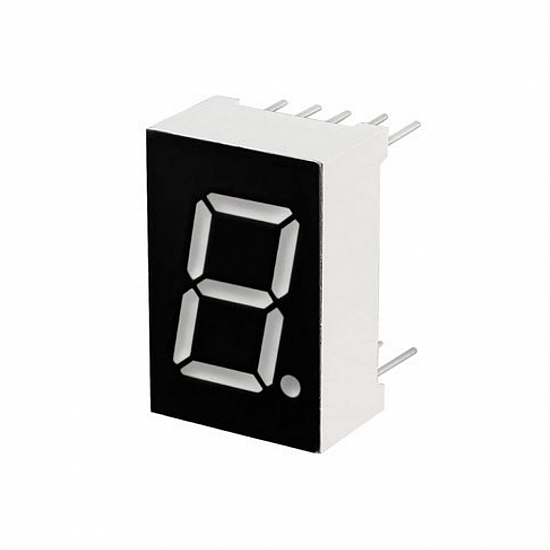
- Single-digit 7-segment LED display
- Common Anode (CA) type
- Red LED segments for high visibility
- Compact and lightweight
- Easy interfacing with microcontrollers like Arduino
- Low power consumption
Specifications
- Model: LD-5161
- Type: Common Anode
- Emitted Color: Red
- Pin Number: 10
- Pin Pitch: 2mm / 0.08"
- Size (excluding pins): 19 x 13 x 7mm / 0.7" x 0.5" x 0.3" (L×W×H)
- Digital Tube Height: 14.2mm / 0.56"
- Material: Plastic, Metal
- Color of LED: Red
- Net Weight: 22g
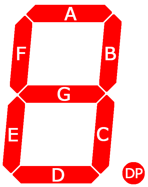
How 7-Segment Displays Work
7-segment displays are foundational components in digital electronics, providing visual representation for numerical digits and select alphabets. Each display consists of seven LED segments arranged in a figure-eight pattern, with an additional eighth segment often serving as a decimal point. Segments are labeled A through G, with the eighth segment marked as DP (decimal point). Functionality-wise, these displays allow for individual control of each segment, similar to standard LEDs.
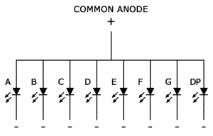
Exploring Common Anode Displays
In common anode displays, all anodes are connected to a positive voltage source (Vcc). Segment activation is achieved by grounding the cathodes. Applying voltage to the desired segments while keeping the common anode connected to Vcc illuminates the corresponding segments, effectively displaying the desired numeral or character.
Pinout
| Pin | Segment |
|---|---|
| 1 | F |
| 2 | A |
| 3 | B |
| 4 | DP (Decimal Point) |
| 5 | C |
| 6 | D |
| 7 | E |
| 8 | Common Anode (VCC) |
Arduino UNO Connections
Use current-limiting resistors (220Ω–330Ω) in series with each segment:
| 7-Segment Pin | Arduino Pin | Description |
|---|---|---|
| A | D2 | Segment A |
| B | D3 | Segment B |
| C | D4 | Segment C |
| D | D5 | Segment D |
| E | D6 | Segment E |
| F | D7 | Segment F |
| G | D8 | Segment G |
| DP | D9 | Decimal Point (optional) |
| Common Anode | +5V | Power Supply |
Arduino Code Example
// 7-Segment Common Anode Example

// Segment pins
int segA = 2;
int segB = 3;
int segC = 4;
int segD = 5;
int segE = 6;
int segF = 7;
int segG = 8;
int segDP = 9; // Optional

// Digit patterns for 0-9 (Common Anode: LOW = ON, HIGH = OFF)
byte digits[10][7] = {
  {LOW, LOW, LOW, LOW, LOW, LOW, HIGH}, // 0
  {HIGH, LOW, LOW, HIGH, HIGH, HIGH, HIGH}, // 1
  {LOW, LOW, HIGH, LOW, LOW, HIGH, LOW}, // 2
  {LOW, LOW, LOW, LOW, HIGH, HIGH, LOW}, // 3
  {HIGH, LOW, LOW, HIGH, HIGH, LOW, LOW}, // 4
  {LOW, HIGH, LOW, LOW, HIGH, LOW, LOW}, // 5
  {LOW, HIGH, LOW, LOW, LOW, LOW, LOW}, // 6
  {LOW, LOW, LOW, HIGH, HIGH, HIGH, HIGH}, // 7
  {LOW, LOW, LOW, LOW, LOW, LOW, LOW}, // 8
  {LOW, LOW, LOW, LOW, HIGH, LOW, LOW}  // 9
};

void setup() {
  int pins[] = {segA, segB, segC, segD, segE, segF, segG};
  for(int i=0; i<7; i++){
    pinMode(pins[i], OUTPUT);
  }
  pinMode(segDP, OUTPUT);
  digitalWrite(segDP, HIGH); // Turn off DP by default
}

void loop() {
  int number = 0;
  for(number=0; number<=9; number++){
    displayDigit(number);
    delay(1000);
  }
}

void displayDigit(int num){
  int pins[] = {segA, segB, segC, segD, segE, segF, segG};
  for(int i=0; i<7; i++){
    digitalWrite(pins[i], digits[num][i]);
  }
}
Features
- Single-digit 7-segment LED display
- Common Anode (CA) type
- Red LED segments for high visibility
- Compact and lightweight
- Easy interfacing with microcontrollers like Arduino
- Low power consumption
Specifications
- Model: LD-5161
- Type: Common Anode
- Emitted Color: Red
- Pin Number: 10
- Pin Pitch: 2mm / 0.08"
- Size (excluding pins): 19 x 13 x 7mm / 0.7" x 0.5" x 0.3" (L×W×H)
- Digital Tube Height: 14.2mm / 0.56"
- Material: Plastic, Metal
- Color of LED: Red
- Net Weight: 22g
How 7-Segment Displays Work
7-segment displays are foundational components in digital electronics, providing visual representation for numerical digits and select alphabets. Each display consists of seven LED segments arranged in a figure-eight pattern, with an additional eighth segment often serving as a decimal point. Segments are labeled A through G, with the eighth segment marked as DP (decimal point). Functionality-wise, these displays allow for individual control of each segment, similar to standard LEDs.
Exploring Common Anode Displays
In common anode displays, all anodes are connected to a positive voltage source (Vcc). Segment activation is achieved by grounding the cathodes. Applying voltage to the desired segments while keeping the common anode connected to Vcc illuminates the corresponding segments, effectively displaying the desired numeral or character.
Pinout
| Pin | Segment |
|---|---|
| 1 | F |
| 2 | A |
| 3 | B |
| 4 | DP (Decimal Point) |
| 5 | C |
| 6 | D |
| 7 | E |
| 8 | Common Anode (VCC) |
Arduino UNO Connections
Use current-limiting resistors (220Ω–330Ω) in series with each segment:
| 7-Segment Pin | Arduino Pin | Description |
|---|---|---|
| A | D2 | Segment A |
| B | D3 | Segment B |
| C | D4 | Segment C |
| D | D5 | Segment D |
| E | D6 | Segment E |
| F | D7 | Segment F |
| G | D8 | Segment G |
| DP | D9 | Decimal Point (optional) |
| Common Anode | +5V | Power Supply |
Arduino Code Example
// 7-Segment Common Anode Example

// Segment pins
int segA = 2;
int segB = 3;
int segC = 4;
int segD = 5;
int segE = 6;
int segF = 7;
int segG = 8;
int segDP = 9; // Optional

// Digit patterns for 0-9 (Common Anode: LOW = ON, HIGH = OFF)
byte digits[10][7] = {
  {LOW, LOW, LOW, LOW, LOW, LOW, HIGH}, // 0
  {HIGH, LOW, LOW, HIGH, HIGH, HIGH, HIGH}, // 1
  {LOW, LOW, HIGH, LOW, LOW, HIGH, LOW}, // 2
  {LOW, LOW, LOW, LOW, HIGH, HIGH, LOW}, // 3
  {HIGH, LOW, LOW, HIGH, HIGH, LOW, LOW}, // 4
  {LOW, HIGH, LOW, LOW, HIGH, LOW, LOW}, // 5
  {LOW, HIGH, LOW, LOW, LOW, LOW, LOW}, // 6
  {LOW, LOW, LOW, HIGH, HIGH, HIGH, HIGH}, // 7
  {LOW, LOW, LOW, LOW, LOW, LOW, LOW}, // 8
  {LOW, LOW, LOW, LOW, HIGH, LOW, LOW}  // 9
};

void setup() {
  int pins[] = {segA, segB, segC, segD, segE, segF, segG};
  for(int i=0; i<7; i++){
    pinMode(pins[i], OUTPUT);
  }
  pinMode(segDP, OUTPUT);
  digitalWrite(segDP, HIGH); // Turn off DP by default
}

void loop() {
  int number = 0;
  for(number=0; number<=9; number++){
    displayDigit(number);
    delay(1000);
  }
}

void displayDigit(int num){
  int pins[] = {segA, segB, segC, segD, segE, segF, segG};
  for(int i=0; i<7; i++){
    digitalWrite(pins[i], digits[num][i]);
  }
}