This relay can be used to control small motors, incandescent lamps, solenoid valves, electromagnetic contactors, low-power power supplies, and intelligent instruments. Its robust internal structure and carefully selected plastic materials ensure excellent heat resistance and chemical durability.
Features
- SPDT contacts with high switching capacity up to 20A
- 24V DC coil voltage
- Compact size suitable for high-density PCB layouts
- Sealed construction for harsh environments
- Low-cost magnetic circuit design for mass production
- High-temperature and chemical-resistant plastic housing
- Long electrical and mechanical service life
- Blue color housing
Specifications
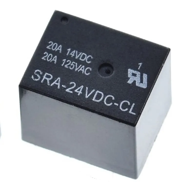
- Relay Model: SRA-24VDC-CL
- Contact Type: SPDT (Switching)
- Number of Pins: 5
- Coil Voltage: 24V DC
- Maximum Contact Current: 20A
- Maximum Contact Voltage: 125V AC / 14V DC
- Power Consumption: 0.60W
- Coil Resistance: 960Ω
- Dimensions: 16 × 12.4 × 17.2 mm
Principle of Operation
When a 24V DC voltage is applied across the relay coil, the internal iron core becomes magnetized, generating a magnetic field. This magnetic force pulls the armature toward the core, changing the state of the contacts. Depending on the wiring, the load circuit connected to the Normally Open (NO) contact will close, or the Normally Closed (NC) contact will open. When the coil voltage is removed, a spring returns the armature to its original position, restoring the contacts to their default state.
Pinout
| Pin Name | Description |
|---|---|
| Coil End 1 | One end of the 24V DC coil (connect to 24V or GND) |
| Coil End 2 | Other end of the 24V DC coil (connect to GND or 24V) |
| COM (Common) | Common terminal connected to the load |
| NC (Normally Closed) | Connected to COM when the relay is not energized |
| NO (Normally Open) | Connected to COM only when the relay is energized |
Applications
- ON/OFF switching applications
- Motor and lighting control
- Home appliances (washing machines, refrigerators)
- Solenoid valves and electromagnetic contactors
- Industrial automation and machinery
- Traffic signal and temperature controllers
- Automotive, aerospace, and defense systems
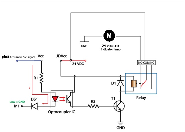
Arduino Example Circuit
In this example, an Arduino controls a transistor (or optocoupler + transistor) to energize the 24V relay coil. When the Arduino outputs HIGH on digital pin 3, the relay activates and supplies 24V to a motor. When the pin goes LOW, the relay deactivates and the motor stops.
Arduino Code Example
This relay does not require any special library.
void setup() {
  pinMode(3, OUTPUT);   // Relay control pin
}

void loop() {
  digitalWrite(3, HIGH); // Turn relay ON (motor runs)
  delay(1000);           // Run for 1 second

  digitalWrite(3, LOW);  // Turn relay OFF (motor stops)
  delay(1000);           // Stop for 1 second
}
Technical Notes
- Always use a transistor or relay driver circuit when controlling the relay from a microcontroller
- Include a flyback diode across the relay coil to protect the driver transistor
- Ensure the load voltage and current do not exceed relay ratings
Comparison Note
Electromechanical relays like the SRA-24VDC-CL use coils, magnetic fields, springs, and mechanical contacts to switch loads, providing full electrical isolation between control and load circuits. Unlike solid-state relays (SSR), mechanical relays can handle much higher surge and continuous currents. SSRs have no moving parts and use semiconductor devices for switching, but typically support lower current ratings at higher cost.
This relay can be used to control small motors, incandescent lamps, solenoid valves, electromagnetic contactors, low-power power supplies, and intelligent instruments. Its robust internal structure and carefully selected plastic materials ensure excellent heat resistance and chemical durability.
Features
- SPDT contacts with high switching capacity up to 20A
- 24V DC coil voltage
- Compact size suitable for high-density PCB layouts
- Sealed construction for harsh environments
- Low-cost magnetic circuit design for mass production
- High-temperature and chemical-resistant plastic housing
- Long electrical and mechanical service life
- Blue color housing
Specifications
- Relay Model: SRA-24VDC-CL
- Contact Type: SPDT (Switching)
- Number of Pins: 5
- Coil Voltage: 24V DC
- Maximum Contact Current: 20A
- Maximum Contact Voltage: 125V AC / 14V DC
- Power Consumption: 0.60W
- Coil Resistance: 960Ω
- Dimensions: 16 × 12.4 × 17.2 mm
Principle of Operation
When a 24V DC voltage is applied across the relay coil, the internal iron core becomes magnetized, generating a magnetic field. This magnetic force pulls the armature toward the core, changing the state of the contacts. Depending on the wiring, the load circuit connected to the Normally Open (NO) contact will close, or the Normally Closed (NC) contact will open. When the coil voltage is removed, a spring returns the armature to its original position, restoring the contacts to their default state.
Pinout
| Pin Name | Description |
|---|---|
| Coil End 1 | One end of the 24V DC coil (connect to 24V or GND) |
| Coil End 2 | Other end of the 24V DC coil (connect to GND or 24V) |
| COM (Common) | Common terminal connected to the load |
| NC (Normally Closed) | Connected to COM when the relay is not energized |
| NO (Normally Open) | Connected to COM only when the relay is energized |
Applications
- ON/OFF switching applications
- Motor and lighting control
- Home appliances (washing machines, refrigerators)
- Solenoid valves and electromagnetic contactors
- Industrial automation and machinery
- Traffic signal and temperature controllers
- Automotive, aerospace, and defense systems
Arduino Example Circuit
In this example, an Arduino controls a transistor (or optocoupler + transistor) to energize the 24V relay coil. When the Arduino outputs HIGH on digital pin 3, the relay activates and supplies 24V to a motor. When the pin goes LOW, the relay deactivates and the motor stops.
Arduino Code Example
This relay does not require any special library.
void setup() {
  pinMode(3, OUTPUT);   // Relay control pin
}

void loop() {
  digitalWrite(3, HIGH); // Turn relay ON (motor runs)
  delay(1000);           // Run for 1 second

  digitalWrite(3, LOW);  // Turn relay OFF (motor stops)
  delay(1000);           // Stop for 1 second
}
Technical Notes
- Always use a transistor or relay driver circuit when controlling the relay from a microcontroller
- Include a flyback diode across the relay coil to protect the driver transistor
- Ensure the load voltage and current do not exceed relay ratings
Comparison Note
Electromechanical relays like the SRA-24VDC-CL use coils, magnetic fields, springs, and mechanical contacts to switch loads, providing full electrical isolation between control and load circuits. Unlike solid-state relays (SSR), mechanical relays can handle much higher surge and continuous currents. SSRs have no moving parts and use semiconductor devices for switching, but typically support lower current ratings at higher cost.