Features
- ARM Cortex M7 processor running at up to 600 MHz
- High performance computing in a very small form factor
- Large onboard memory for complex applications
- Wide range of digital, analog, and PWM input output pins
- USB, Ethernet, and CAN bus connectivity support
- High speed SD card access for data storage
- Compatible with Arduino IDE and Teensyduino
- Low power consumption relative to performance
- Strong community support with many libraries and tools
Specifications
- Processor ARM Cortex M7
- Clock speed up to 600 MHz
- Flash memory 1984 KB
- RAM 1024 KB
- Operating voltage 3.3 V
- Digital input output pins up to 40
- Analog input pins up to 14
- PWM output pins up to 31
- USB device and host support
- Ethernet and CAN bus support
- Board dimensions approximately 1.4 x 0.7 inches
Principle of Work
The Teensy 4.0 operates by executing code stored in its flash memory using the ARM Cortex M7 processor. When powered on, the program is loaded into RAM and executed at high speed. The processor communicates with onboard peripherals such as digital and analog pins, timers, communication interfaces, and memory to perform tasks defined by the user code. High clock speed and advanced architecture allow complex calculations, real time signal processing, and fast communication with external devices.
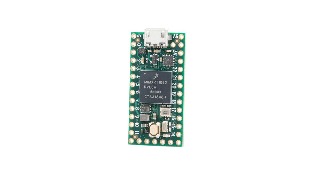
Pinout

- 3.3V regulated output for external components
- AREF analog reference voltage input
- Analog pins A0 to A15 for sensor input
- Digital pins 0 to 35 for input and output
- PWM pins for motor and LED control
- TX and RX pins for multiple serial interfaces
- SDA and SCL pins for I2C communication
- MOSI MISO and SCK pins for SPI communication
- CAN bus pins for industrial and automotive use
- Dedicated pins for Ethernet and SD card access
Applications
- Robotics and motor control systems
- Audio processing and digital signal processing
- Internet of Things devices
- Automation and control systems
- Machine learning and data processing
- Gaming controllers and custom hardware
Arduino IDE Setup
- Install the Arduino IDE on your computer
- Download and install Teensyduino from the PJRC website
- Select Teensy 4.0 from the Board menu
- Select the correct USB port
- Write and upload your sketch to the board
Example Arduino Code
const int ledPin = 14;

void setup() {
  pinMode(ledPin, OUTPUT);
}

void loop() {
  digitalWrite(ledPin, HIGH);
  delay(500);
  digitalWrite(ledPin, LOW);
  delay(500);
}
Circuit Connection
Connect an LED in series with a 220 ohm resistor to pin 14 and ground. This simple circuit allows you to test basic digital output functionality by blinking the LED.
Technical Details
- ARM Cortex M7 at 600 MHz
- Floating point unit support
- Multiple serial SPI and I2C interfaces
- CAN bus and digital audio interfaces
- Real time clock and hardware random number generator
- Advanced DMA and peripheral triggering
Features
- ARM Cortex M7 processor running at up to 600 MHz
- High performance computing in a very small form factor
- Large onboard memory for complex applications
- Wide range of digital, analog, and PWM input output pins
- USB, Ethernet, and CAN bus connectivity support
- High speed SD card access for data storage
- Compatible with Arduino IDE and Teensyduino
- Low power consumption relative to performance
- Strong community support with many libraries and tools
Specifications
- Processor ARM Cortex M7
- Clock speed up to 600 MHz
- Flash memory 1984 KB
- RAM 1024 KB
- Operating voltage 3.3 V
- Digital input output pins up to 40
- Analog input pins up to 14
- PWM output pins up to 31
- USB device and host support
- Ethernet and CAN bus support
- Board dimensions approximately 1.4 x 0.7 inches
Principle of Work
The Teensy 4.0 operates by executing code stored in its flash memory using the ARM Cortex M7 processor. When powered on, the program is loaded into RAM and executed at high speed. The processor communicates with onboard peripherals such as digital and analog pins, timers, communication interfaces, and memory to perform tasks defined by the user code. High clock speed and advanced architecture allow complex calculations, real time signal processing, and fast communication with external devices.
Pinout
- 3.3V regulated output for external components
- AREF analog reference voltage input
- Analog pins A0 to A15 for sensor input
- Digital pins 0 to 35 for input and output
- PWM pins for motor and LED control
- TX and RX pins for multiple serial interfaces
- SDA and SCL pins for I2C communication
- MOSI MISO and SCK pins for SPI communication
- CAN bus pins for industrial and automotive use
- Dedicated pins for Ethernet and SD card access
Applications
- Robotics and motor control systems
- Audio processing and digital signal processing
- Internet of Things devices
- Automation and control systems
- Machine learning and data processing
- Gaming controllers and custom hardware
Arduino IDE Setup
- Install the Arduino IDE on your computer
- Download and install Teensyduino from the PJRC website
- Select Teensy 4.0 from the Board menu
- Select the correct USB port
- Write and upload your sketch to the board
Example Arduino Code
const int ledPin = 14;

void setup() {
  pinMode(ledPin, OUTPUT);
}

void loop() {
  digitalWrite(ledPin, HIGH);
  delay(500);
  digitalWrite(ledPin, LOW);
  delay(500);
}
Circuit Connection
Connect an LED in series with a 220 ohm resistor to pin 14 and ground. This simple circuit allows you to test basic digital output functionality by blinking the LED.
Technical Details
- ARM Cortex M7 at 600 MHz
- Floating point unit support
- Multiple serial SPI and I2C interfaces
- CAN bus and digital audio interfaces
- Real time clock and hardware random number generator
- Advanced DMA and peripheral triggering