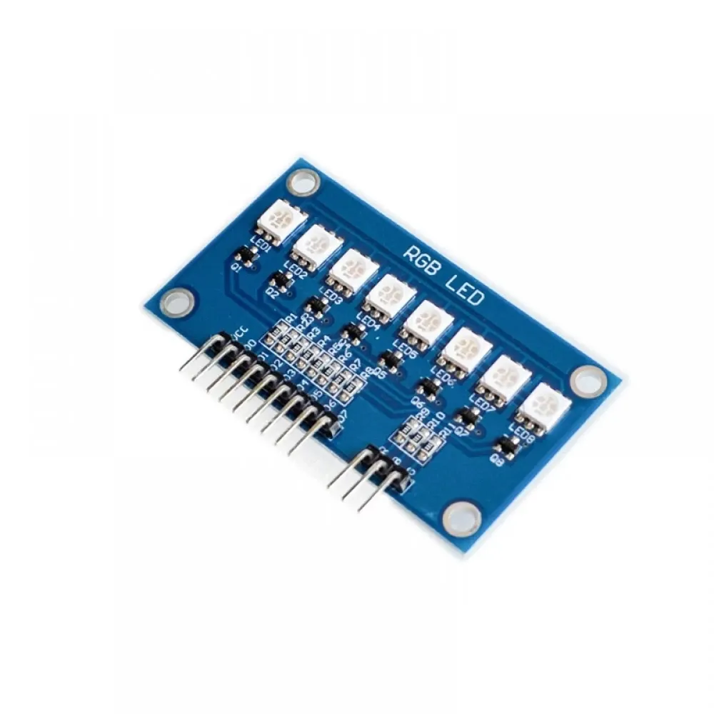
Features
- LEDs: 8 RGB LEDs with scanning control.
- Control: Digital pins D0-D7 for individual LED selection.
- Compatibility: 51/AVR/ARM/Arduino platforms.
- PWM Color Control: Separate pins for R, G, B channels.
Pinout

| Pin |
Description |
| VCC |
Power Supply (Connect to +5V) |
| D0 - D7 |
LED Control (Drive LOW to activate respective LED) |
| R |
Red channel control (PWM) |
| G |
Green channel control (PWM) |
| B |
Blue channel control (PWM) |
How It Works
- LED Control: Drive pins D0-D7 LOW to turn on specific LEDs.
- Color Selection: Adjust R, G, B channels via PWM for desired colors.
- Scanning Control: LEDs are scanned sequentially to create smooth transitions and patterns.
- Microcontroller Compatibility: Works with Arduino, AVR, ARM, and similar platforms.
Arduino Wiring
- Connect VCC to 5V on Arduino.
- Connect GND to Arduino GND.
- Connect D0–D7 to digital pins on Arduino (example: 2-9).
- Connect R, G, B pins to PWM-capable Arduino pins (example: 10, 11, 12).
Example Arduino Code
int ledPins[] = {2, 3, 4, 5, 6, 7, 8, 9}; // D0-D7
int redPin = 10;
int greenPin = 11;
int bluePin = 12;
void setup() {
 for(int i = 0; i < 8; i++) {
 pinMode(ledPins[i], OUTPUT);
 digitalWrite(ledPins[i], HIGH); // LEDs off initially
 }
 pinMode(redPin, OUTPUT);
 pinMode(greenPin, OUTPUT);
 pinMode(bluePin, OUTPUT);
}
void loop() {
 // Example: Turn on LED 0 with red color
 digitalWrite(ledPins[0], LOW); // Activate LED 0
 analogWrite(redPin, 255); // Full red
 analogWrite(greenPin, 0);
 analogWrite(bluePin, 0);
 delay(1000);
 // Turn off LED 0
 digitalWrite(ledPins[0], HIGH);
 delay(500);
 // Example: LED 1 green
 digitalWrite(ledPins[1], LOW);
 analogWrite(redPin, 0);
 analogWrite(greenPin, 255);
 analogWrite(bluePin, 0);
 delay(1000);
 digitalWrite(ledPins[1], HIGH);
 delay(500);
}
Features
- LEDs: 8 RGB LEDs with scanning control.
- Control: Digital pins D0-D7 for individual LED selection.
- Compatibility: 51/AVR/ARM/Arduino platforms.
- PWM Color Control: Separate pins for R, G, B channels.
Pinout
| Pin |
Description |
| VCC |
Power Supply (Connect to +5V) |
| D0 - D7 |
LED Control (Drive LOW to activate respective LED) |
| R |
Red channel control (PWM) |
| G |
Green channel control (PWM) |
| B |
Blue channel control (PWM) |
How It Works
- LED Control: Drive pins D0-D7 LOW to turn on specific LEDs.
- Color Selection: Adjust R, G, B channels via PWM for desired colors.
- Scanning Control: LEDs are scanned sequentially to create smooth transitions and patterns.
- Microcontroller Compatibility: Works with Arduino, AVR, ARM, and similar platforms.
Arduino Wiring
- Connect VCC to 5V on Arduino.
- Connect GND to Arduino GND.
- Connect D0–D7 to digital pins on Arduino (example: 2-9).
- Connect R, G, B pins to PWM-capable Arduino pins (example: 10, 11, 12).
Example Arduino Code
int ledPins[] = {2, 3, 4, 5, 6, 7, 8, 9}; // D0-D7
int redPin = 10;
int greenPin = 11;
int bluePin = 12;
void setup() {
 for(int i = 0; i < 8; i++) {
 pinMode(ledPins[i], OUTPUT);
 digitalWrite(ledPins[i], HIGH); // LEDs off initially
 }
 pinMode(redPin, OUTPUT);
 pinMode(greenPin, OUTPUT);
 pinMode(bluePin, OUTPUT);
}
void loop() {
 // Example: Turn on LED 0 with red color
 digitalWrite(ledPins[0], LOW); // Activate LED 0
 analogWrite(redPin, 255); // Full red
 analogWrite(greenPin, 0);
 analogWrite(bluePin, 0);
 delay(1000);
 // Turn off LED 0
 digitalWrite(ledPins[0], HIGH);
 delay(500);
 // Example: LED 1 green
 digitalWrite(ledPins[1], LOW);
 analogWrite(redPin, 0);
 analogWrite(greenPin, 255);
 analogWrite(bluePin, 0);
 delay(1000);
 digitalWrite(ledPins[1], HIGH);
 delay(500);
}