Features:
-
Microcontroller AVR AT2560 (8bit)
-
Power Supply 7-9V
-
Digital I/O Pins 54
-
Analog I/O Pins 16
-
Total Digital I/O 70 (Digital + Analog)
-
Clock Speed 16 MHz
-
Flash Memory 128 KB
-
SRAM 8 KB
-
No USB or onboard programmer.
-
ICSP (programming), SPI, I2C and USART
-
Timer 2 (8bit) + 4 (16bit) = 6 timer
-
WM 12 (2-16 bit)ADC 16 (10 bit)
-
USART 4Pin
-
Change Interrupt 24
Principle of Work:
Arduino is Free hardware, anything whose blueprints and specs are available for anybody to copy. This means that Arduino provides the framework so that any other individual or business can design their own boards, each of which can be unique yet function well when built upon the same framework. Free software is a computer program whose source code is available to anybody, allowing them to use and alter it as they see fit. In order to allow anyone to create apps for Arduino boards and provide them with a variety of utilities, Arduino provides the Arduino IDE (Integrated Development Environment) platform. which you can use to program and upload your code (sketch) and do this using an External Serial Converter with the help of an embedded bootloader, the Arduino uses libraries that can be downloaded online and gives you the ability to program a significant number of sensor and module without even knowing how they really work.
Pinout of the Module:
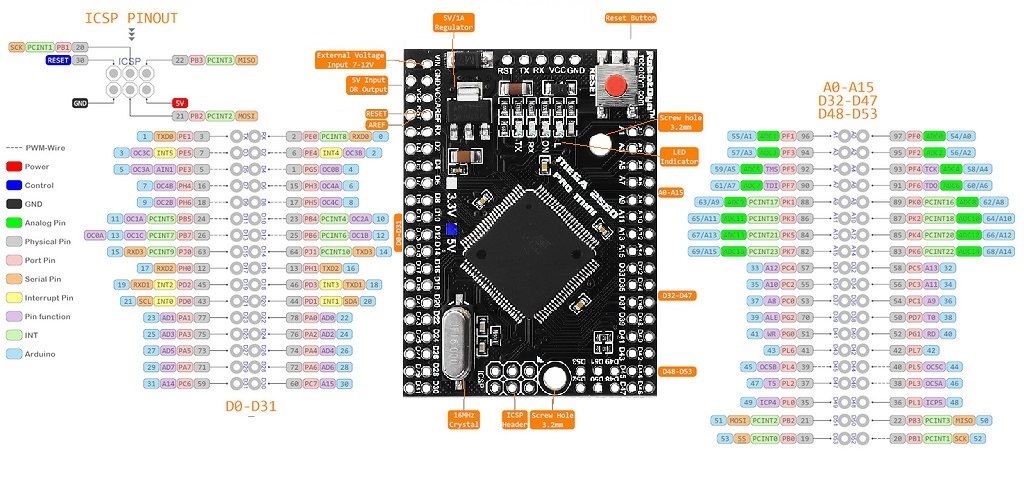
Arduino Mega Pro Mini Overview
Digital I/O
| Feature | Description |
|---|---|
| Digital Pins | 54 digital I/O pins, 15 with PWM capability. Can be configured as input (read 0 or 1) or output (drive LEDs, relays, modules). Functions: pinMode(), digitalWrite(), digitalRead() |
| GND | Ground pins for circuits and voltage stability |
| AREF | Analog reference voltage (0–5V). Used with analogReference() to set top of analog input range |
| SDA | I²C Data line |
| SCL | I²C Clock line |
| ICSP Header | In-Circuit Serial Programming for firmware updates. Pins: MOSI, MISO, SCK, RESET, VCC, GND |
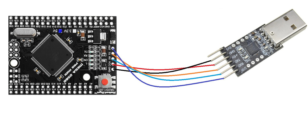
| No USB | Board lacks USB interface; requires USB-TTL converter for PC connection |
| D13 LED | Onboard LED connected to pin 13. HIGH = ON, LOW = OFF |
| TX LED | Flashes when serial data is transmitted |
| RX LED | Flashes when serial data is received |
| Crystal Oscillator | 16 MHz timing oscillator for Arduino operations |
| Voltage Regulator | Stabilizes input DC voltage (7–9V) to 5V for processor and peripherals |
| IOREF | Provides operating voltage for shields (3.3V or 5V) |
| RESET Button | Resets the board and restarts the program |
| RESET Header | Connect an external reset button |
| 3V3 | 3.3V output, max 50 mA |
| 5V | 5V output |
| Vin | External DC input 7–9V |
| Analog Pins | 16 analog inputs labeled A0–A15 |
| Power LED | Indicates correct power connection. OFF = power problem |
| ATMega Pro Mini 16U2-MU | USB-to-serial chip converting USB signals to serial for the microcontroller |
Applications:
- Weighing Machines.
- Traffic Light Count Down Timer.
- Parking Lot Counter.
- Embedded systems.
- Home Automation.
- Industrial Automation.
- Medical Instrument.
- Emergency Light for Railways.
Circuit:
We will not need any circuit, in this testing code, we will rely on the built-in LED on the 13th pin.
Connecting with Arduino First Time
1. Open Arduino IDE
If you haven’t done so already, download Arduino IDE from the software page.
2. Connect the board to your computer
The board doesn't have USB interface. For connecting to the PC, pls use the USB-TTL converter.
3. Select Board
- Next, you need to tell Arduino IDE which board your sketch is for.
- Click on Tools in the menu bar and find the Board row. If a board is currently selected it will be displayed here.
- The tools menu with the Board row is highlighted.
- Hover over the Board row to reveal the installed board packages. These packages contain some popular boards.
- Click on a board to select it.
- Selecting a board in Arduino IDE.
4. Select port
- Click on Tools in the menu bar and find the Port row. If a board is currently selected it will be displayed here.
- The tools menu with the Port row highlighted.
- Hover over the Port to reveal all ports. For Arduino devices, the board name will typically be displayed after the port.
- Port naming varies by system:
- Windows: COM3 (Arduino Mega Pro Mini )
- macOS: /dev/cu.usbmodem14101 (Arduino Mega Pro Mini )
- Linux: /dev/ttyACM0 (Arduino Mega Pro Mini )
- Click on a port to select it. If the port with your board is already selected you don’t have to do anything. If you don’t see your board in the list, see If your board does not appear in the port menu.
- Selecting a port in Arduino IDE.
- Troubleshooting: If you don’t see your board in the list, see If your board does not appear in the port menu.
5. Upload a sketch
- Write a sketch, or use an Example such as Blink (File > Examples > 01. Basics > Blink).
- Optional: Click the Verify button to try compiling the sketch and check for errors.
- Click the Upload button to program the board with the sketch.
- Your sketch will start running on the board. It will run again each time the board is reset.
Code:
void setup() {
pinMode(13,1);
}
void loop() {
digitalWrite(13,1);
delay(1000);
digitalWrite(13,0);
delay(1000); }
Technical Details:
- Microcontroller: ATMega Pro Mini 2560
- Microcontroller Clock Speed 16MHz
- Operating Voltage +5V
- Input Voltage(recommended) +7~+9V
- Output Voltage +5V, +3.3V
- Digital I/O Pins 54
- PWM Digital I/O Pins 15
- Analog Input Pins 16
- Analog Output Pins
- Rated Current per Pin 20mA/Pin
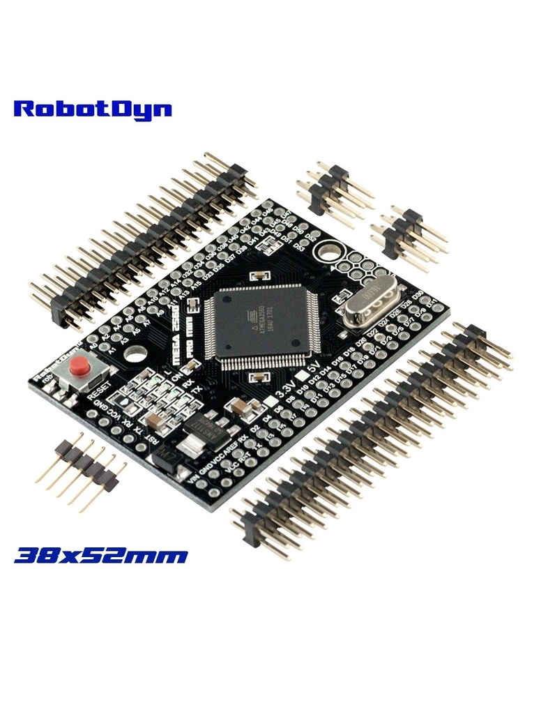
- Dimensions: ~ 38x52mm
Resources:
Comparisons:
Both the Mega Pro Mini and Uno have a clock speed of 16MHz, however, they have different amounts of memory and storage. Uno has 32kB of flash memory, while Mega Pro Mini has 256kB. Mega Pro Mini is preferred if the code is large due to the RAM. Arduino Boards make use of SRAM. Mega Pro Mini has 8kB of SRAM space in the system, compared to Uno's 2kB. The Mega Pro Mini has a total of 54 digital pins and 16 analog pins. On Uno, there are only 14 digital pins and 6 analog pins. In Mega Pro Mini, PWM is present on 15 digital pins as opposed to 6 in Uno. Every one of them includes a through-hole pin header for inserting DuPont wires into the Board. so if you have a project that needs a flash space and a high number of pins Mega Pro Mini is your choice. and this version of Arduino Mega is just so small at 38x52 in comparison to regular mega with ~ 50 x 100mm but doesn't forget this board has no programmer so this is a little bit harder for beginner so if you are a beginner we are recommending the normal mega to
Features:
-
Microcontroller AVR AT2560 (8bit)
-
Power Supply 7-9V
-
Digital I/O Pins 54
-
Analog I/O Pins 16
-
Total Digital I/O 70 (Digital + Analog)
-
Clock Speed 16 MHz
-
Flash Memory 128 KB
-
SRAM 8 KB
-
No USB or onboard programmer.
-
ICSP (programming), SPI, I2C and USART
-
Timer 2 (8bit) + 4 (16bit) = 6 timer
-
WM 12 (2-16 bit)ADC 16 (10 bit)
-
USART 4Pin
-
Change Interrupt 24
Principle of Work:
Arduino is Free hardware, anything whose blueprints and specs are available for anybody to copy. This means that Arduino provides the framework so that any other individual or business can design their own boards, each of which can be unique yet function well when built upon the same framework. Free software is a computer program whose source code is available to anybody, allowing them to use and alter it as they see fit. In order to allow anyone to create apps for Arduino boards and provide them with a variety of utilities, Arduino provides the Arduino IDE (Integrated Development Environment) platform. which you can use to program and upload your code (sketch) and do this using an External Serial Converter with the help of an embedded bootloader, the Arduino uses libraries that can be downloaded online and gives you the ability to program a significant number of sensor and module without even knowing how they really work.
Pinout of the Module:
Arduino Mega Pro Mini Overview
Digital I/O
| Feature | Description |
|---|---|
| Digital Pins | 54 digital I/O pins, 15 with PWM capability. Can be configured as input (read 0 or 1) or output (drive LEDs, relays, modules). Functions: pinMode(), digitalWrite(), digitalRead() |
| GND | Ground pins for circuits and voltage stability |
| AREF | Analog reference voltage (0–5V). Used with analogReference() to set top of analog input range |
| SDA | I²C Data line |
| SCL | I²C Clock line |
| ICSP Header | In-Circuit Serial Programming for firmware updates. Pins: MOSI, MISO, SCK, RESET, VCC, GND |
| No USB | Board lacks USB interface; requires USB-TTL converter for PC connection |
| D13 LED | Onboard LED connected to pin 13. HIGH = ON, LOW = OFF |
| TX LED | Flashes when serial data is transmitted |
| RX LED | Flashes when serial data is received |
| Crystal Oscillator | 16 MHz timing oscillator for Arduino operations |
| Voltage Regulator | Stabilizes input DC voltage (7–9V) to 5V for processor and peripherals |
| IOREF | Provides operating voltage for shields (3.3V or 5V) |
| RESET Button | Resets the board and restarts the program |
| RESET Header | Connect an external reset button |
| 3V3 | 3.3V output, max 50 mA |
| 5V | 5V output |
| Vin | External DC input 7–9V |
| Analog Pins | 16 analog inputs labeled A0–A15 |
| Power LED | Indicates correct power connection. OFF = power problem |
| ATMega Pro Mini 16U2-MU | USB-to-serial chip converting USB signals to serial for the microcontroller |
Applications:
- Weighing Machines.
- Traffic Light Count Down Timer.
- Parking Lot Counter.
- Embedded systems.
- Home Automation.
- Industrial Automation.
- Medical Instrument.
- Emergency Light for Railways.
Circuit:
We will not need any circuit, in this testing code, we will rely on the built-in LED on the 13th pin.
Connecting with Arduino First Time
1. Open Arduino IDE
If you haven’t done so already, download Arduino IDE from the software page.
2. Connect the board to your computer
The board doesn't have USB interface. For connecting to the PC, pls use the USB-TTL converter.
3. Select Board
- Next, you need to tell Arduino IDE which board your sketch is for.
- Click on Tools in the menu bar and find the Board row. If a board is currently selected it will be displayed here.
- The tools menu with the Board row is highlighted.
- Hover over the Board row to reveal the installed board packages. These packages contain some popular boards.
- Click on a board to select it.
- Selecting a board in Arduino IDE.
4. Select port
- Click on Tools in the menu bar and find the Port row. If a board is currently selected it will be displayed here.
- The tools menu with the Port row highlighted.
- Hover over the Port to reveal all ports. For Arduino devices, the board name will typically be displayed after the port.
- Port naming varies by system:
- Windows: COM3 (Arduino Mega Pro Mini )
- macOS: /dev/cu.usbmodem14101 (Arduino Mega Pro Mini )
- Linux: /dev/ttyACM0 (Arduino Mega Pro Mini )
- Click on a port to select it. If the port with your board is already selected you don’t have to do anything. If you don’t see your board in the list, see If your board does not appear in the port menu.
- Selecting a port in Arduino IDE.
- Troubleshooting: If you don’t see your board in the list, see If your board does not appear in the port menu.
5. Upload a sketch
- Write a sketch, or use an Example such as Blink (File > Examples > 01. Basics > Blink).
- Optional: Click the Verify button to try compiling the sketch and check for errors.
- Click the Upload button to program the board with the sketch.
- Your sketch will start running on the board. It will run again each time the board is reset.
Code:
void setup() {
pinMode(13,1);
}
void loop() {
digitalWrite(13,1);
delay(1000);
digitalWrite(13,0);
delay(1000); }
Technical Details:
- Microcontroller: ATMega Pro Mini 2560
- Microcontroller Clock Speed 16MHz
- Operating Voltage +5V
- Input Voltage(recommended) +7~+9V
- Output Voltage +5V, +3.3V
- Digital I/O Pins 54
- PWM Digital I/O Pins 15
- Analog Input Pins 16
- Analog Output Pins
- Rated Current per Pin 20mA/Pin
- Dimensions: ~ 38x52mm
Resources:
Comparisons:
Both the Mega Pro Mini and Uno have a clock speed of 16MHz, however, they have different amounts of memory and storage. Uno has 32kB of flash memory, while Mega Pro Mini has 256kB. Mega Pro Mini is preferred if the code is large due to the RAM. Arduino Boards make use of SRAM. Mega Pro Mini has 8kB of SRAM space in the system, compared to Uno's 2kB. The Mega Pro Mini has a total of 54 digital pins and 16 analog pins. On Uno, there are only 14 digital pins and 6 analog pins. In Mega Pro Mini, PWM is present on 15 digital pins as opposed to 6 in Uno. Every one of them includes a through-hole pin header for inserting DuPont wires into the Board. so if you have a project that needs a flash space and a high number of pins Mega Pro Mini is your choice. and this version of Arduino Mega is just so small at 38x52 in comparison to regular mega with ~ 50 x 100mm but doesn't forget this board has no programmer so this is a little bit harder for beginner so if you are a beginner we are recommending the normal mega to