Features
-
Microcontroller: AVR ATtiny85 (8-bit)
-
Color: Black
-
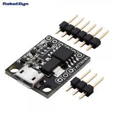
Model: Digispark ATtiny85 (micro-USB)
-
Clock Frequency: Up to 20 MHz
-
Interface: Micro-USB
-
Flash Memory: 8 KB (6 KB usable)
-
SRAM: 512 B
-
EEPROM: 512 B
-
I/O Pins: 6
-
PWM Pins: 2
-
ADC Pins: 4
-
Hardware Interfaces:
-
Onboard Power LED and Status LED
-
Voltage Regulator: 5V
Principle of Work
This board is built on open hardware and free software principles.
-
Compatible with Arduino IDE.
-
Supports embedded USB functionality using V-USB.
-
Can be extended using open-source libraries and examples.
Pinout

| Function |
Pins |
| GPIO |
P0, P1, P2, P3, P4, P5 (6 GPIO) |
| SPI |
MOSI (P0), MISO (P1), SCK (P2) |
| PWM |
P0, P1, P3, P4 (4 PWM) |
| ADC |
A1, A3, A4, A5 (4 ADC) |
| I2C |
SDA (P0), SCL (P2) |
I/O and Interfaces
-
Digital I/O: 6 pins (4 PWM-capable)
-
Analog Pins: 4 analog inputs
-
GND: Ground pin
-
AREF: Analog reference voltage (0–5V)
-
SDA/SCL: I2C communication pins
-
USB: Software USB via V-USB
-
Onboard LED: Controlled via pin 1
-
Voltage Regulator: Converts 7–12V to 5V
-
Power Pins:
-
5V: Output
-
VIN: 7–12V input
-
Power LED: Confirms power supply status
Applications
Testing Circuit
No additional circuit needed — uses built-in LED on pin 1.
Getting Started
1. Install Arduino IDE
Download Arduino IDE
2. Connect the Board to Your PC
3. Add Board Manager URL
4. Install Board Package
5. Install Drivers (Windows 10)
6. Select Board
7. Upload Sketch
-
Disconnect the board first
-
Write or load a sketch
-
Click Upload, then connect the board when prompted
-
Code runs after a 5-second boot delay
Example Code
void setup() {
  pinMode(1, OUTPUT); // Onboard LED connected to pin 1
}

void loop() {
  digitalWrite(1, HIGH);
  delay(200);
  digitalWrite(1, LOW);
  delay(200);
}
Technical Details
-
Microcontroller: ATtiny85
-
Clock Speed: 16.5 MHz
-
Operating Voltage: 5V
-
Max Output Current: 800 mA
-
Input Voltage (recommended): 7–12V
-
Output Voltage: 5V
-
Digital I/O Pins: 6
-
Rated Current per Pin: 20 mA
-
Low Power:
-
300 μA @ 1.8V active
-
0.1 μA @ 1.8V sleep
-
Temperature Range: -40°C to +105°C
-
USB Input: 5V
-
VIN Input: 6–12V
-
Logic Level Voltage: 5V
-
Dimensions: 18×21×2 mm
-
Weight: 3 g
Resources
Comparison
Compared to the Arduino Uno:
-
Weaker performance, but
-
USB emulation support (via V-USB)
-
Smaller and cheaper
-
Built-in LDO regulator
-
Ideal for compact, simple projects
-
Not recommended for complete beginners
Features
-
Microcontroller: AVR ATtiny85 (8-bit)
-
Color: Black
-
Model: Digispark ATtiny85 (micro-USB)
-
Clock Frequency: Up to 20 MHz
-
Interface: Micro-USB
-
Flash Memory: 8 KB (6 KB usable)
-
SRAM: 512 B
-
EEPROM: 512 B
-
I/O Pins: 6
-
PWM Pins: 2
-
ADC Pins: 4
-
Hardware Interfaces:
-
Onboard Power LED and Status LED
-
Voltage Regulator: 5V
Principle of Work
This board is built on open hardware and free software principles.
-
Compatible with Arduino IDE.
-
Supports embedded USB functionality using V-USB.
-
Can be extended using open-source libraries and examples.
Pinout

| Function |
Pins |
| GPIO |
P0, P1, P2, P3, P4, P5 (6 GPIO) |
| SPI |
MOSI (P0), MISO (P1), SCK (P2) |
| PWM |
P0, P1, P3, P4 (4 PWM) |
| ADC |
A1, A3, A4, A5 (4 ADC) |
| I2C |
SDA (P0), SCL (P2) |
I/O and Interfaces
-
Digital I/O: 6 pins (4 PWM-capable)
-
Analog Pins: 4 analog inputs
-
GND: Ground pin
-
AREF: Analog reference voltage (0–5V)
-
SDA/SCL: I2C communication pins
-
USB: Software USB via V-USB
-
Onboard LED: Controlled via pin 1
-
Voltage Regulator: Converts 7–12V to 5V
-
Power Pins:
-
5V: Output
-
VIN: 7–12V input
-
Power LED: Confirms power supply status
Applications
Testing Circuit
No additional circuit needed — uses built-in LED on pin 1.
Getting Started
1. Install Arduino IDE
Download Arduino IDE
2. Connect the Board to Your PC
3. Add Board Manager URL
4. Install Board Package
5. Install Drivers (Windows 10)
6. Select Board
7. Upload Sketch
-
Disconnect the board first
-
Write or load a sketch
-
Click Upload, then connect the board when prompted
-
Code runs after a 5-second boot delay
Example Code
void setup() {
  pinMode(1, OUTPUT); // Onboard LED connected to pin 1
}

void loop() {
  digitalWrite(1, HIGH);
  delay(200);
  digitalWrite(1, LOW);
  delay(200);
}
Technical Details
-
Microcontroller: ATtiny85
-
Clock Speed: 16.5 MHz
-
Operating Voltage: 5V
-
Max Output Current: 800 mA
-
Input Voltage (recommended): 7–12V
-
Output Voltage: 5V
-
Digital I/O Pins: 6
-
Rated Current per Pin: 20 mA
-
Low Power:
-
300 μA @ 1.8V active
-
0.1 μA @ 1.8V sleep
-
Temperature Range: -40°C to +105°C
-
USB Input: 5V
-
VIN Input: 6–12V
-
Logic Level Voltage: 5V
-
Dimensions: 18×21×2 mm
-
Weight: 3 g
Resources
Comparison
Compared to the Arduino Uno:
-
Weaker performance, but
-
USB emulation support (via V-USB)
-
Smaller and cheaper
-
Built-in LDO regulator
-
Ideal for compact, simple projects
-
Not recommended for complete beginners

