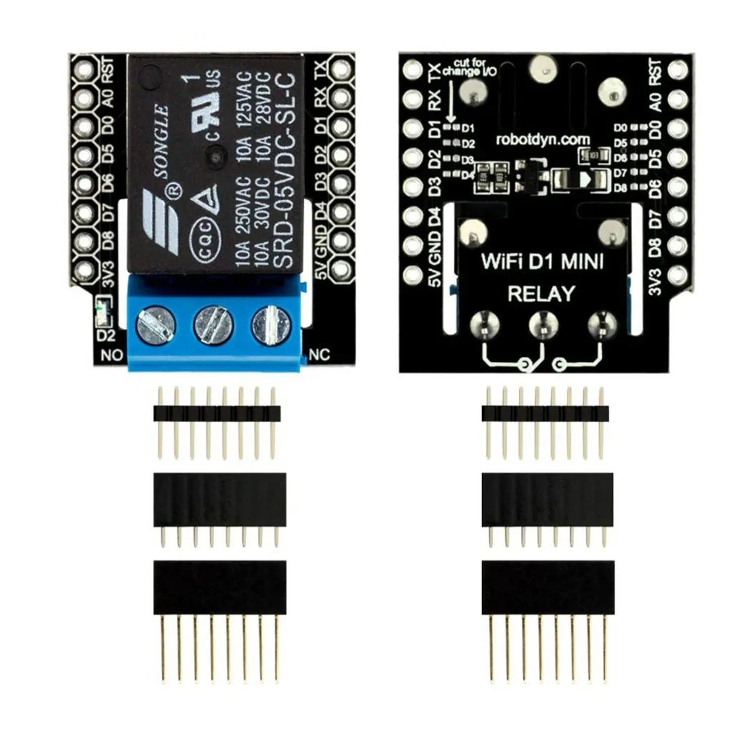

Features
- Compatible with WeMos D1 Mini and D1 Mini PRO
- Onboard electromechanical relay
- Default control via D1 GPIO
- Selectable control pin (modifiable solder pad)
- Suitable for AC and DC load control
- Stackable shield design
Specifications
- Control Circuit Voltage: 5V DC
- Relay Type: Single-channel mechanical relay
- Maximum Load Voltage: 110/220V AC or 30V DC
- Maximum Load Current: 10A
- Trigger Signal: Digital I/O (3.3V logic compatible via D1 Mini)
- Mounting Format: D1 Mini shield standard
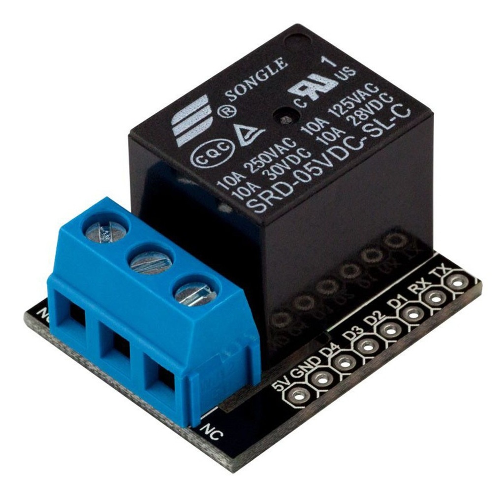
Pinout
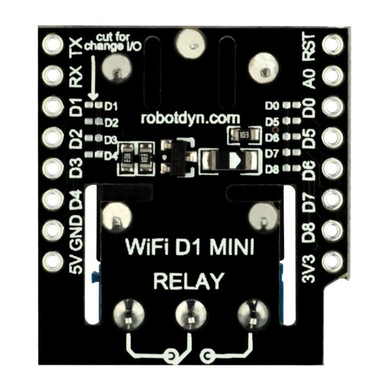
- D1 – Default relay control pin (GPIO5)
- 5V – Power supply from D1 Mini
- GND – Ground
- COM – Common terminal (load side)
- NO – Normally Open contact
- NC – Normally Closed contact
Library Support
- No dedicated relay library required
- Controlled using standard digitalWrite() function
- Compatible with ESP8266 Arduino core
Connection
- Mount shield directly onto D1 Mini or D1 Mini PRO
- Connect AC/DC load to COM and NO or NC terminals
- Power D1 Mini via USB or 5V input
- Control relay using assigned GPIO in code
Schematics
- GPIO pin connected to transistor driver circuit
- Relay coil powered by 5V rail
- Flyback diode protection across relay coil
- COM/NO/NC screw terminal block for load connection
Applications
- Smart home automation
- Remote light switching
- IoT-based appliance control
- Industrial prototype switching
- Garage door or gate control systems
Resources & Libraries
- Arduino IDE: https://www.arduino.cc/en/software
- ESP8266 Arduino Core: https://github.com/esp8266/Arduino
- ESP8266 GPIO Reference: https://arduino-esp8266.readthedocs.io/
- Relay Safety Guidelines (general reference): https://www.electronics-tutorials.ws/blog/relay-switch-circuit.html
Features
- Compatible with WeMos D1 Mini and D1 Mini PRO
- Onboard electromechanical relay
- Default control via D1 GPIO
- Selectable control pin (modifiable solder pad)
- Suitable for AC and DC load control
- Stackable shield design
Specifications
- Control Circuit Voltage: 5V DC
- Relay Type: Single-channel mechanical relay
- Maximum Load Voltage: 110/220V AC or 30V DC
- Maximum Load Current: 10A
- Trigger Signal: Digital I/O (3.3V logic compatible via D1 Mini)
- Mounting Format: D1 Mini shield standard
Pinout
- D1 – Default relay control pin (GPIO5)
- 5V – Power supply from D1 Mini
- GND – Ground
- COM – Common terminal (load side)
- NO – Normally Open contact
- NC – Normally Closed contact
Library Support
- No dedicated relay library required
- Controlled using standard digitalWrite() function
- Compatible with ESP8266 Arduino core
Connection
- Mount shield directly onto D1 Mini or D1 Mini PRO
- Connect AC/DC load to COM and NO or NC terminals
- Power D1 Mini via USB or 5V input
- Control relay using assigned GPIO in code
Schematics
- GPIO pin connected to transistor driver circuit
- Relay coil powered by 5V rail
- Flyback diode protection across relay coil
- COM/NO/NC screw terminal block for load connection
Applications
- Smart home automation
- Remote light switching
- IoT-based appliance control
- Industrial prototype switching
- Garage door or gate control systems
Resources & Libraries
- Arduino IDE: https://www.arduino.cc/en/software
- ESP8266 Arduino Core: https://github.com/esp8266/Arduino
- ESP8266 GPIO Reference: https://arduino-esp8266.readthedocs.io/
- Relay Safety Guidelines (general reference): https://www.electronics-tutorials.ws/blog/relay-switch-circuit.html