
Features
- Integrated WiFi SoC: Self-contained System-on-Chip design.
- 802.11 b/g/n Support: Reliable 2.4GHz WiFi connectivity.
- Standalone Operation: Can act as a microcontroller.
- Multiple GPIOs: Depending on firmware, up to 9 GPIOs supported.
- AT Command Support: Easily controlled via serial interface.
- Compact Size: Ideal for space-constrained applications.
Specifications
- Chipset: ESP8266
- WiFi Standard: 802.11 b/g/n (2.4GHz)
- Operating Voltage: 3.3V DC
- Logic Level: 3.3V (Not 5V tolerant)
- Communication: UART (Serial)
- Flash Memory: Typically 1MB (varies by version)
- Modes: Station (STA), Access Point (AP), STA+AP
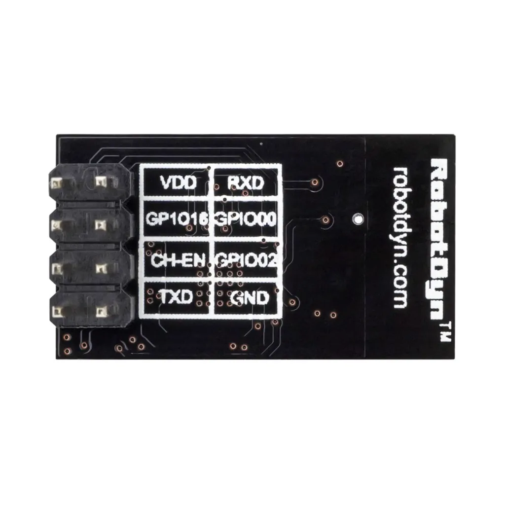
Pinout
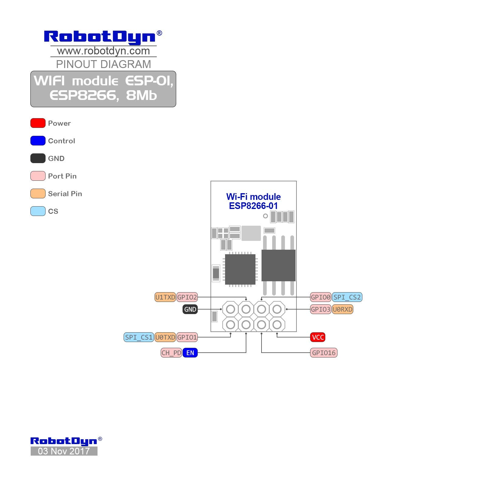
| Pin | Description |
|---|---|
| VCC | 3.3V Power Supply |
| GND | Ground |
| TX | UART Transmit |
| RX | UART Receive |
| CH_PD / EN | Chip Enable (Pull HIGH to enable) |
| GPIO0 | General Purpose I/O (Used for flashing) |
| GPIO2 | General Purpose I/O |
| RST | Reset |
Operating Modes
- Station (STA): Connects to an existing WiFi network.
- Access Point (AP): Creates its own WiFi network.
- STA + AP: Works in both modes simultaneously.
Typical Applications
- IoT devices
- Wireless sensor networks
- Home automation
- Remote monitoring systems
- Web server projects
How to to work with Arduino:
Step 1: Install Arduino IDE
Download and install Arduino IDE.
Step 2: Add ESP8266 Board URL
File → Preferences → "Additional Boards Manager URLs":
http://arduino.esp8266.com/stable/package_esp8266com_index.json
Step 3: Install ESP8266 Boards
Tools → Board → Boards Manager → Search "ESP8266" → Install "esp8266 by ESP8266 Community"
Step 4: Select ESP-01 Board
Tools → Board → ESP8266 Modules → Generic ESP8266 Module
Flash Size: 1MB (8Mb), Upload Speed: 115200
Step 5: Connect ESP-01
-
VCC → 3.3V
-
GND → GND
-
TX → RX, RX → TX
-
CH_PD → 3.3V
-
GPIO0 → GND (for programming)
Step 6: Upload Example
File → Examples → ESP8266 → Blink → Upload
After upload, disconnect GPIO0 from GND and reset ESP-01
Step 7: Use WiFi
Use the WiFi library in sketches to connect to your network.
Basic AT Command Example (Arduino)
#define WIFI_NAME "Your_WiFi_Name"
#define WIFI_PASS "Your_WiFi_Password"

void setup() {
  Serial.begin(115200);
  delay(2000);

  Serial.println("AT");               // Test communication
  delay(1000);

  Serial.println("AT+CWMODE=1");      // Set to Station mode
  delay(2000);

  Serial.print("AT+CWJAP=\"");
  Serial.print(WIFI_NAME);
  Serial.print("\",\"");
  Serial.print(WIFI_PASS);
  Serial.println("\"");               // Connect to WiFi
  delay(5000);

  Serial.println("AT+CIPMUX=1");      // Enable multiple connections
  delay(1000);

  Serial.println("AT+CIPSERVER=1,80"); // Start server on port 80
}

void loop() {
}
Important Notes
- Always use a stable 3.3V power supply (minimum 300mA recommended).
- Do NOT connect directly to 5V logic without level shifting.
- GPIO0 must be LOW during boot for flashing firmware.
Features
- Integrated WiFi SoC: Self-contained System-on-Chip design.
- 802.11 b/g/n Support: Reliable 2.4GHz WiFi connectivity.
- Standalone Operation: Can act as a microcontroller.
- Multiple GPIOs: Depending on firmware, up to 9 GPIOs supported.
- AT Command Support: Easily controlled via serial interface.
- Compact Size: Ideal for space-constrained applications.
Specifications
- Chipset: ESP8266
- WiFi Standard: 802.11 b/g/n (2.4GHz)
- Operating Voltage: 3.3V DC
- Logic Level: 3.3V (Not 5V tolerant)
- Communication: UART (Serial)
- Flash Memory: Typically 1MB (varies by version)
- Modes: Station (STA), Access Point (AP), STA+AP
Pinout
| Pin | Description |
|---|---|
| VCC | 3.3V Power Supply |
| GND | Ground |
| TX | UART Transmit |
| RX | UART Receive |
| CH_PD / EN | Chip Enable (Pull HIGH to enable) |
| GPIO0 | General Purpose I/O (Used for flashing) |
| GPIO2 | General Purpose I/O |
| RST | Reset |
Operating Modes
- Station (STA): Connects to an existing WiFi network.
- Access Point (AP): Creates its own WiFi network.
- STA + AP: Works in both modes simultaneously.
Typical Applications
- IoT devices
- Wireless sensor networks
- Home automation
- Remote monitoring systems
- Web server projects
How to to work with Arduino:
Step 1: Install Arduino IDE
Download and install Arduino IDE.
Step 2: Add ESP8266 Board URL
File → Preferences → "Additional Boards Manager URLs":
http://arduino.esp8266.com/stable/package_esp8266com_index.json
Step 3: Install ESP8266 Boards
Tools → Board → Boards Manager → Search "ESP8266" → Install "esp8266 by ESP8266 Community"
Step 4: Select ESP-01 Board
Tools → Board → ESP8266 Modules → Generic ESP8266 Module
Flash Size: 1MB (8Mb), Upload Speed: 115200
Step 5: Connect ESP-01
-
VCC → 3.3V
-
GND → GND
-
TX → RX, RX → TX
-
CH_PD → 3.3V
-
GPIO0 → GND (for programming)
Step 6: Upload Example
File → Examples → ESP8266 → Blink → Upload
After upload, disconnect GPIO0 from GND and reset ESP-01
Step 7: Use WiFi
Use the WiFi library in sketches to connect to your network.
Basic AT Command Example (Arduino)
#define WIFI_NAME "Your_WiFi_Name"
#define WIFI_PASS "Your_WiFi_Password"

void setup() {
  Serial.begin(115200);
  delay(2000);

  Serial.println("AT");               // Test communication
  delay(1000);

  Serial.println("AT+CWMODE=1");      // Set to Station mode
  delay(2000);

  Serial.print("AT+CWJAP=\"");
  Serial.print(WIFI_NAME);
  Serial.print("\",\"");
  Serial.print(WIFI_PASS);
  Serial.println("\"");               // Connect to WiFi
  delay(5000);

  Serial.println("AT+CIPMUX=1");      // Enable multiple connections
  delay(1000);

  Serial.println("AT+CIPSERVER=1,80"); // Start server on port 80
}

void loop() {
}
Important Notes
- Always use a stable 3.3V power supply (minimum 300mA recommended).
- Do NOT connect directly to 5V logic without level shifting.
- GPIO0 must be LOW during boot for flashing firmware.