Features
- ATmega32U4 Microcontroller: 8-bit AVR microcontroller operating at 16 MHz, with native USB functionality.
- W5500 Ethernet Controller: Provides 10/100 Mbps Ethernet connectivity with an integrated hardware TCP/IP protocol stack.
- Digital I/O: 20 digital input/output pins available through the board's connectors.
- PWM Outputs: 7 digital pins support 8-bit PWM output.
- Analog Inputs: 12 analog input channels with 10-bit resolution.
- Hardware Interrupts: External interrupt support on selected digital pins.
- USB Connectivity: Micro-USB port for programming, serial communication, and USB HID applications.
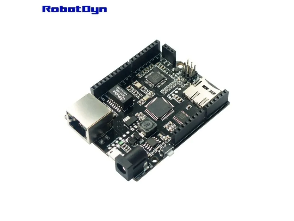
- Ethernet Connector: RJ45 connector for wired network communication.
- microSD Card Socket: Supports local data storage and retrieval.
- SPI Interface: Connects the ATmega32U4 to the W5500 and microSD card interface.
- HID Functionality: Supports USB keyboard and mouse emulation through the Arduino Keyboard and Mouse libraries.
- External Power: DC power jack and VIN connection for an external supply.
- Without PoE: The Ethernet connection does not provide Power over Ethernet; the board requires a separate power source.
Principle of Operation
The RobotDyn Leonardo ETH (V2) combines two main processing components: the ATmega32U4 microcontroller and the Wiznet W5500 Ethernet controller.

- ATmega32U4: Executes the Arduino sketch, reads sensors, controls digital and analog I/O, and manages connected peripherals.
- W5500 Ethernet Controller: Handles Ethernet communication and implements hardware TCP/IP processing for network applications. It supports 10Base-T and 100Base-TX Ethernet operation.
- SPI Communication: The ATmega32U4 communicates with the W5500 through SPI. The microSD card interface also uses the SPI bus, with separate chip-select signals.
- microSD Storage: A microSD card can be used to store sensor readings, event records, configuration data, and other files for later retrieval or network transfer.
The W5500 handles network protocol processing, while the ATmega32U4 runs the application logic. This arrangement allows the board to perform control tasks while communicating with other devices over an Ethernet network.
Pinout
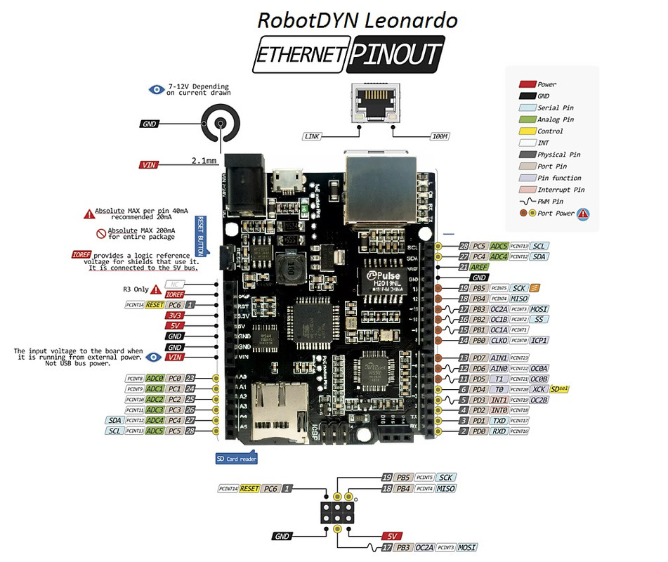
Digital and Analog Pins
- 20 digital I/O pins are available through the board connectors.
- 12 analog input channels are available, identified as A0 to A11.
- Analog inputs use a 10-bit ADC resolution, providing readings from 0 to 1023.
- The standard I/O logic level is 5V.
- Internal pull-up resistors can be enabled through the Arduino pin configuration functions.
PWM Pins
- PWM output is available on digital pins D3, D5, D6, D9, D10, D11, and D13.
- PWM output can be controlled using the Arduino
analogWrite()function. - The standard PWM resolution is 8-bit.
SPI Interface
- The SPI bus is available through the ICSP connector and the board's SPI connections.
- SPI signals include MISO, MOSI, and SCK.
- The W5500 Ethernet controller and microSD card interface share the SPI bus and use separate chip-select signals.
- The board provides additional SPI-related connections identified as D14, D15, and D16. Refer to the supplied pinout diagram for their exact functions.
UART Serial Communication
- D0 (RX) and D1 (TX) provide the hardware UART interface.
- Use
Serial1for communication through the RX and TX pins. - Use
Serialfor USB serial communication with a connected computer.
I2C / TWI Interface
- SDA and SCL provide the I2C communication interface.
- The Arduino
Wirelibrary can be used to communicate with I2C sensors and peripherals. - Use the board's marked SDA and SCL connections when wiring I2C devices.
Ethernet and microSD Connections
- RJ45: Ethernet network connection through the W5500 controller.
- W5500: Communicates with the ATmega32U4 through SPI.
- microSD socket: Provides removable storage using the SPI interface.
- D10 and D4 are identified as chip-select connections for the Ethernet and microSD interfaces respectively in the supplied board pinout.
- Some additional pins may be reserved for Ethernet control, card detection, or interrupt functions. Check the board diagram before using these pins for other peripherals.
Power Pins
- VIN: External unregulated power input. The board's supplied technical information specifies a 7–24V input range; confirm the acceptable input range for the particular board revision before applying power.
- 5V: Regulated 5V rail. Do not apply an external voltage to this pin unless it is a properly regulated 5V supply and the board's power arrangement is understood.
- 3.3V: 3.3V supply output for compatible peripherals, subject to the board regulator's current limit.
- GND: Common ground connection.
- RST: Reset input. Pulling this pin LOW resets the microcontroller.
- IOREF: Indicates the board's I/O operating voltage.
LED Indicators
- ON: Indicates that the board is powered.
- L: Built-in LED connected to digital pin D13.
- RX/TX: Indicate serial communication activity where supported by the board design.
Applications
- Ethernet-Based IoT: Connect sensors and embedded devices to a wired network.
- Remote Monitoring: Collect sensor readings and make data available to network-connected systems.
- Industrial Automation: Develop Ethernet-connected monitoring and control interfaces.
- Data Logging: Store measurements, events, and system records on a microSD card.
- Networked Control Systems: Exchange data with computers, servers, and other Ethernet devices.
- Web-Controlled Projects: Develop network-accessible control interfaces and embedded web applications.
- USB HID Projects: Build custom USB keyboards, mouse controllers, and other HID devices.
- Prototyping: Develop embedded applications combining microcontroller I/O, Ethernet communication, and local storage.
Getting Started
- Install Arduino IDE: Download and install the Arduino IDE from the Arduino Software page.
- Connect the Board: Connect the RobotDyn Leonardo ETH (V2) to your computer using a suitable data-capable Micro-USB cable.
- Select the Board: In Arduino IDE, open Tools > Board and select Arduino Leonardo if the board is compatible with the standard Leonardo board definition.
- Select the Port: Open Tools > Port and select the serial port assigned to the board.
- Install Ethernet Library: For W5500 network applications, install or use an Ethernet library that supports the W5500 controller.
- Upload a Sketch: Verify the sketch, then click Upload to program the board.
- Monitor Serial Output: Open the Serial Monitor to view messages sent through the USB serial connection.
The board uses the ATmega32U4's native USB interface. The serial port may briefly disconnect or change during reset and uploading.
Code
The following example blinks the built-in LED on pin 13 and sends status messages to the Arduino IDE Serial Monitor over USB.
const int ledPin = 13;

void setup() {
  pinMode(ledPin, OUTPUT);
  Serial.begin(9600);
}

void loop() {
  digitalWrite(ledPin, HIGH);
  Serial.println("LED ON");
  delay(1000);

  digitalWrite(ledPin, LOW);
  Serial.println("LED OFF");
  delay(1000);
}Upload the sketch with Arduino Leonardo selected. Open the Serial Monitor to view the LED status messages. This example tests the microcontroller and USB serial connection; it does not test Ethernet communication or the microSD interface.
Specifications
- Main Microcontroller: ATmega32U4
- Microcontroller Architecture: 8-bit AVR
- Clock Speed: 16 MHz
- Operating Voltage: 5V
- Digital I/O Pins: 20
- PWM Outputs: 7
- Analog Inputs: 12
- ADC Resolution: 10-bit
- Flash Memory: 32 KB (4 KB used by the bootloader)
- SRAM: 2.5 KB
- EEPROM: 1 KB
- USB Interface: Native USB through ATmega32U4
- USB Connector: Micro-USB
- Ethernet Controller: Wiznet W5500
- Ethernet Speed: 10/100 Mbps
- Ethernet Interface: RJ45
- Ethernet Controller Clock: 25 MHz
- Ethernet Supply Voltage: 3.3V
- Ethernet Protocol Support: TCP, UDP, IPv4, ICMP, ARP, IGMP, and PPPoE
- Storage: microSD card socket
- External Power Input: VIN / DC jack; supplied product information specifies 7–24V
- Board Dimensions: Approximately 53.3 × 68.6 mm
- Weight: Approximately 41 g
Note: The input-voltage range, connector assignments, and reserved Ethernet/microSD pins should be checked against the exact RobotDyn ETH (V2) hardware revision. The board is supplied without PoE functionality.
Comparison: RobotDyn Leonardo ETH (V2) vs. Standard Arduino Leonardo
| Feature | RobotDyn Leonardo ETH (V2) | Standard Arduino Leonardo |
|---|---|---|
| Main Microcontroller | ATmega32U4 | ATmega32U4 |
| USB Connectivity | Native USB | Native USB |
| Ethernet | Wiznet W5500 with RJ45 connector | Not built in |
| microSD Socket | Included | Not included |
| Digital I/O | 20 | 20 |
| PWM Outputs | 7 | 7 |
| Analog Inputs | 12 | 12 |
| Network Communication | Built-in Ethernet hardware | Requires an external network interface |
The RobotDyn Leonardo ETH (V2) retains the main microcontroller features of the standard Leonardo while adding a W5500 Ethernet controller, an RJ45 network connector, and a microSD card socket. It is suitable for projects that require wired network communication and local data storage without adding separate Ethernet and storage modules.
Resources
- Arduino IDE Software
- Arduino Language Reference
- Arduino Leonardo Hardware Documentation
- Wiznet W5500 Documentation
Features
- ATmega32U4 Microcontroller: 8-bit AVR microcontroller operating at 16 MHz, with native USB functionality.
- W5500 Ethernet Controller: Provides 10/100 Mbps Ethernet connectivity with an integrated hardware TCP/IP protocol stack.
- Digital I/O: 20 digital input/output pins available through the board's connectors.
- PWM Outputs: 7 digital pins support 8-bit PWM output.
- Analog Inputs: 12 analog input channels with 10-bit resolution.
- Hardware Interrupts: External interrupt support on selected digital pins.
- USB Connectivity: Micro-USB port for programming, serial communication, and USB HID applications.
- Ethernet Connector: RJ45 connector for wired network communication.
- microSD Card Socket: Supports local data storage and retrieval.
- SPI Interface: Connects the ATmega32U4 to the W5500 and microSD card interface.
- HID Functionality: Supports USB keyboard and mouse emulation through the Arduino Keyboard and Mouse libraries.
- External Power: DC power jack and VIN connection for an external supply.
- Without PoE: The Ethernet connection does not provide Power over Ethernet; the board requires a separate power source.
Principle of Operation
The RobotDyn Leonardo ETH (V2) combines two main processing components: the ATmega32U4 microcontroller and the Wiznet W5500 Ethernet controller.
- ATmega32U4: Executes the Arduino sketch, reads sensors, controls digital and analog I/O, and manages connected peripherals.
- W5500 Ethernet Controller: Handles Ethernet communication and implements hardware TCP/IP processing for network applications. It supports 10Base-T and 100Base-TX Ethernet operation.
- SPI Communication: The ATmega32U4 communicates with the W5500 through SPI. The microSD card interface also uses the SPI bus, with separate chip-select signals.
- microSD Storage: A microSD card can be used to store sensor readings, event records, configuration data, and other files for later retrieval or network transfer.
The W5500 handles network protocol processing, while the ATmega32U4 runs the application logic. This arrangement allows the board to perform control tasks while communicating with other devices over an Ethernet network.
Pinout
Digital and Analog Pins
- 20 digital I/O pins are available through the board connectors.
- 12 analog input channels are available, identified as A0 to A11.
- Analog inputs use a 10-bit ADC resolution, providing readings from 0 to 1023.
- The standard I/O logic level is 5V.
- Internal pull-up resistors can be enabled through the Arduino pin configuration functions.
PWM Pins
- PWM output is available on digital pins D3, D5, D6, D9, D10, D11, and D13.
- PWM output can be controlled using the Arduino
analogWrite()function. - The standard PWM resolution is 8-bit.
SPI Interface
- The SPI bus is available through the ICSP connector and the board's SPI connections.
- SPI signals include MISO, MOSI, and SCK.
- The W5500 Ethernet controller and microSD card interface share the SPI bus and use separate chip-select signals.
- The board provides additional SPI-related connections identified as D14, D15, and D16. Refer to the supplied pinout diagram for their exact functions.
UART Serial Communication
- D0 (RX) and D1 (TX) provide the hardware UART interface.
- Use
Serial1for communication through the RX and TX pins. - Use
Serialfor USB serial communication with a connected computer.
I2C / TWI Interface
- SDA and SCL provide the I2C communication interface.
- The Arduino
Wirelibrary can be used to communicate with I2C sensors and peripherals. - Use the board's marked SDA and SCL connections when wiring I2C devices.
Ethernet and microSD Connections
- RJ45: Ethernet network connection through the W5500 controller.
- W5500: Communicates with the ATmega32U4 through SPI.
- microSD socket: Provides removable storage using the SPI interface.
- D10 and D4 are identified as chip-select connections for the Ethernet and microSD interfaces respectively in the supplied board pinout.
- Some additional pins may be reserved for Ethernet control, card detection, or interrupt functions. Check the board diagram before using these pins for other peripherals.
Power Pins
- VIN: External unregulated power input. The board's supplied technical information specifies a 7–24V input range; confirm the acceptable input range for the particular board revision before applying power.
- 5V: Regulated 5V rail. Do not apply an external voltage to this pin unless it is a properly regulated 5V supply and the board's power arrangement is understood.
- 3.3V: 3.3V supply output for compatible peripherals, subject to the board regulator's current limit.
- GND: Common ground connection.
- RST: Reset input. Pulling this pin LOW resets the microcontroller.
- IOREF: Indicates the board's I/O operating voltage.
LED Indicators
- ON: Indicates that the board is powered.
- L: Built-in LED connected to digital pin D13.
- RX/TX: Indicate serial communication activity where supported by the board design.
Applications
- Ethernet-Based IoT: Connect sensors and embedded devices to a wired network.
- Remote Monitoring: Collect sensor readings and make data available to network-connected systems.
- Industrial Automation: Develop Ethernet-connected monitoring and control interfaces.
- Data Logging: Store measurements, events, and system records on a microSD card.
- Networked Control Systems: Exchange data with computers, servers, and other Ethernet devices.
- Web-Controlled Projects: Develop network-accessible control interfaces and embedded web applications.
- USB HID Projects: Build custom USB keyboards, mouse controllers, and other HID devices.
- Prototyping: Develop embedded applications combining microcontroller I/O, Ethernet communication, and local storage.
Getting Started
- Install Arduino IDE: Download and install the Arduino IDE from the Arduino Software page.
- Connect the Board: Connect the RobotDyn Leonardo ETH (V2) to your computer using a suitable data-capable Micro-USB cable.
- Select the Board: In Arduino IDE, open Tools > Board and select Arduino Leonardo if the board is compatible with the standard Leonardo board definition.
- Select the Port: Open Tools > Port and select the serial port assigned to the board.
- Install Ethernet Library: For W5500 network applications, install or use an Ethernet library that supports the W5500 controller.
- Upload a Sketch: Verify the sketch, then click Upload to program the board.
- Monitor Serial Output: Open the Serial Monitor to view messages sent through the USB serial connection.
The board uses the ATmega32U4's native USB interface. The serial port may briefly disconnect or change during reset and uploading.
Code
The following example blinks the built-in LED on pin 13 and sends status messages to the Arduino IDE Serial Monitor over USB.
const int ledPin = 13;

void setup() {
  pinMode(ledPin, OUTPUT);
  Serial.begin(9600);
}

void loop() {
  digitalWrite(ledPin, HIGH);
  Serial.println("LED ON");
  delay(1000);

  digitalWrite(ledPin, LOW);
  Serial.println("LED OFF");
  delay(1000);
}
Upload the sketch with Arduino Leonardo selected. Open the Serial Monitor to view the LED status messages. This example tests the microcontroller and USB serial connection; it does not test Ethernet communication or the microSD interface.
Specifications
- Main Microcontroller: ATmega32U4
- Microcontroller Architecture: 8-bit AVR
- Clock Speed: 16 MHz
- Operating Voltage: 5V
- Digital I/O Pins: 20
- PWM Outputs: 7
- Analog Inputs: 12
- ADC Resolution: 10-bit
- Flash Memory: 32 KB (4 KB used by the bootloader)
- SRAM: 2.5 KB
- EEPROM: 1 KB
- USB Interface: Native USB through ATmega32U4
- USB Connector: Micro-USB
- Ethernet Controller: Wiznet W5500
- Ethernet Speed: 10/100 Mbps
- Ethernet Interface: RJ45
- Ethernet Controller Clock: 25 MHz
- Ethernet Supply Voltage: 3.3V
- Ethernet Protocol Support: TCP, UDP, IPv4, ICMP, ARP, IGMP, and PPPoE
- Storage: microSD card socket
- External Power Input: VIN / DC jack; supplied product information specifies 7–24V
- Board Dimensions: Approximately 53.3 × 68.6 mm
- Weight: Approximately 41 g
Note: The input-voltage range, connector assignments, and reserved Ethernet/microSD pins should be checked against the exact RobotDyn ETH (V2) hardware revision. The board is supplied without PoE functionality.
Comparison: RobotDyn Leonardo ETH (V2) vs. Standard Arduino Leonardo
| Feature | RobotDyn Leonardo ETH (V2) | Standard Arduino Leonardo |
|---|---|---|
| Main Microcontroller | ATmega32U4 | ATmega32U4 |
| USB Connectivity | Native USB | Native USB |
| Ethernet | Wiznet W5500 with RJ45 connector | Not built in |
| microSD Socket | Included | Not included |
| Digital I/O | 20 | 20 |
| PWM Outputs | 7 | 7 |
| Analog Inputs | 12 | 12 |
| Network Communication | Built-in Ethernet hardware | Requires an external network interface |
The RobotDyn Leonardo ETH (V2) retains the main microcontroller features of the standard Leonardo while adding a W5500 Ethernet controller, an RJ45 network connector, and a microSD card socket. It is suitable for projects that require wired network communication and local data storage without adding separate Ethernet and storage modules.