Specifications:
- Frequency Range: Up to 70 MHz
- Waveform Output: 2 Sine Waves, 2 Square Waves
- Data Input: Serial & Parallel (jumper selectable)
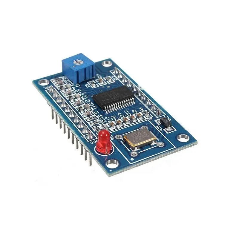
- Chip: AD9850 (Analog Devices Inc.)
- Output Stability: High precision and low noise
- Sine Harmonics: Noticeable above 20–30 MHz
- Voltage Control: Comparator reference via potentiometer
- Compatibility: Easily interfaces with Arduino
Features:
- Generate two sine and two square waveforms
- 70 MHz low-pass filter ensures waveform quality
- Jumper-selectable serial/parallel input for flexibility
- Uses stable and precise AD9850 chip
- Clean sine output up to 30 MHz
- Adjustable square wave duty cycle via comparator reference
- Simple integration with Arduino using labeled pinout
- Wide range of applications from test equipment to RF projects
- Low-noise signal with high frequency accuracy
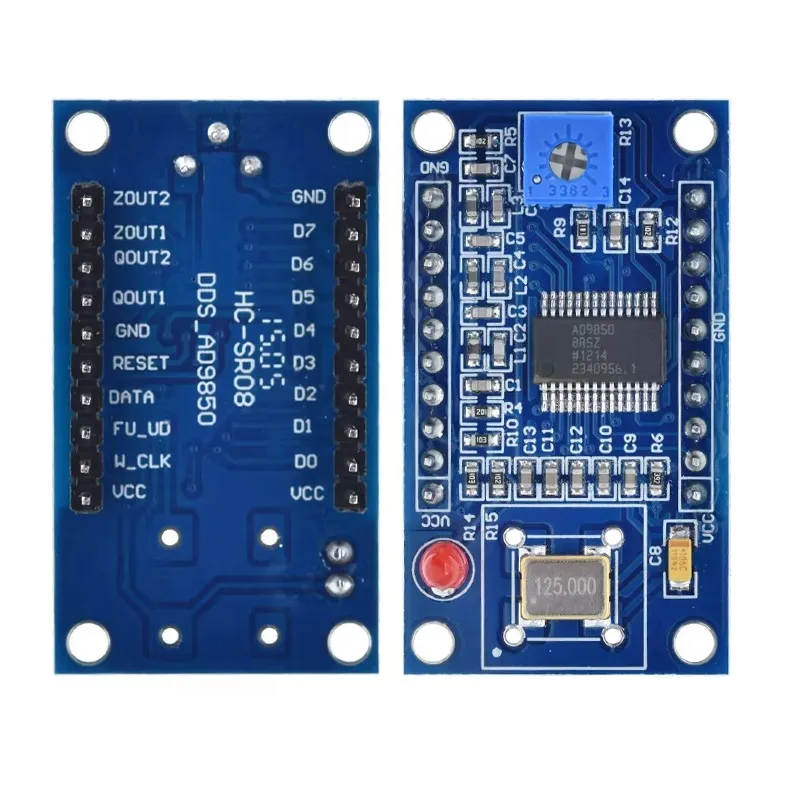
Pinout:
The pin description starts from the left of the potentiometer:
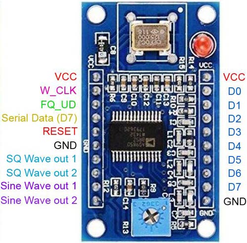
| Pin Name | Type | Description |
|---|---|---|
| VCC | Power | +5V supply input (some boards support 3.3–5V logic) |
| GND | Power | Ground |
| W_CLK | Input | Serial clock input (used to shift data into DDS register) |
| FQ_UD | Input | Frequency update (loads shifted data into active register) |
| DATA | Input | Serial data input (40-bit frequency & control word) |
| RESET | Input | Resets the DDS chip |
| Pin Name | Type | Description |
|---|---|---|
| SINE OUT | Analog Output | Sine wave output (0–40 MHz typical usable range) |
| SQUARE OUT | Digital Output | Square wave output (TTL level) |
What do the D0 to D7 do?
- They form an 8-bit parallel data bus.
- Used to load the 40-bit frequency tuning word (5 bytes total).
- Data is latched using:
- W_CLK (write clock)
- FQ_UD (frequency update)
- RESET
Important Notes
- Most Arduino projects use serial mode (only DATA, W_CLK, FQ_UD, RESET).
- Parallel mode is faster but requires more MCU pins.
- If you're not using parallel control, D0–D7 can remain unconnected.
Downloads:
- AD9852 Datasheet – Complete DDS Synthesizer
- Arduino AD9850 Library with Examples
- Tutorial: AD9850 DDS IC Test Equipment 0-40MHz Sine Square Wave
Specifications:
- Frequency Range: Up to 70 MHz
- Waveform Output: 2 Sine Waves, 2 Square Waves
- Data Input: Serial & Parallel (jumper selectable)
- Chip: AD9850 (Analog Devices Inc.)
- Output Stability: High precision and low noise
- Sine Harmonics: Noticeable above 20–30 MHz
- Voltage Control: Comparator reference via potentiometer
- Compatibility: Easily interfaces with Arduino
Features:
- Generate two sine and two square waveforms
- 70 MHz low-pass filter ensures waveform quality
- Jumper-selectable serial/parallel input for flexibility
- Uses stable and precise AD9850 chip
- Clean sine output up to 30 MHz
- Adjustable square wave duty cycle via comparator reference
- Simple integration with Arduino using labeled pinout
- Wide range of applications from test equipment to RF projects
- Low-noise signal with high frequency accuracy
Pinout:
The pin description starts from the left of the potentiometer:
| Pin Name | Type | Description |
|---|---|---|
| VCC | Power | +5V supply input (some boards support 3.3–5V logic) |
| GND | Power | Ground |
| W_CLK | Input | Serial clock input (used to shift data into DDS register) |
| FQ_UD | Input | Frequency update (loads shifted data into active register) |
| DATA | Input | Serial data input (40-bit frequency & control word) |
| RESET | Input | Resets the DDS chip |
| Pin Name | Type | Description |
|---|---|---|
| SINE OUT | Analog Output | Sine wave output (0–40 MHz typical usable range) |
| SQUARE OUT | Digital Output | Square wave output (TTL level) |
What do the D0 to D7 do?
- They form an 8-bit parallel data bus.
- Used to load the 40-bit frequency tuning word (5 bytes total).
- Data is latched using:
- W_CLK (write clock)
- FQ_UD (frequency update)
- RESET
Important Notes
- Most Arduino projects use serial mode (only DATA, W_CLK, FQ_UD, RESET).
- Parallel mode is faster but requires more MCU pins.
- If you're not using parallel control, D0–D7 can remain unconnected.