In addition to infrared tracking, the module can also function as a flame sensor. It can detect heat sources and determine the position of a flame within its field of view, making it useful for fire alarm systems, safety monitoring, and automated fire detection projects.
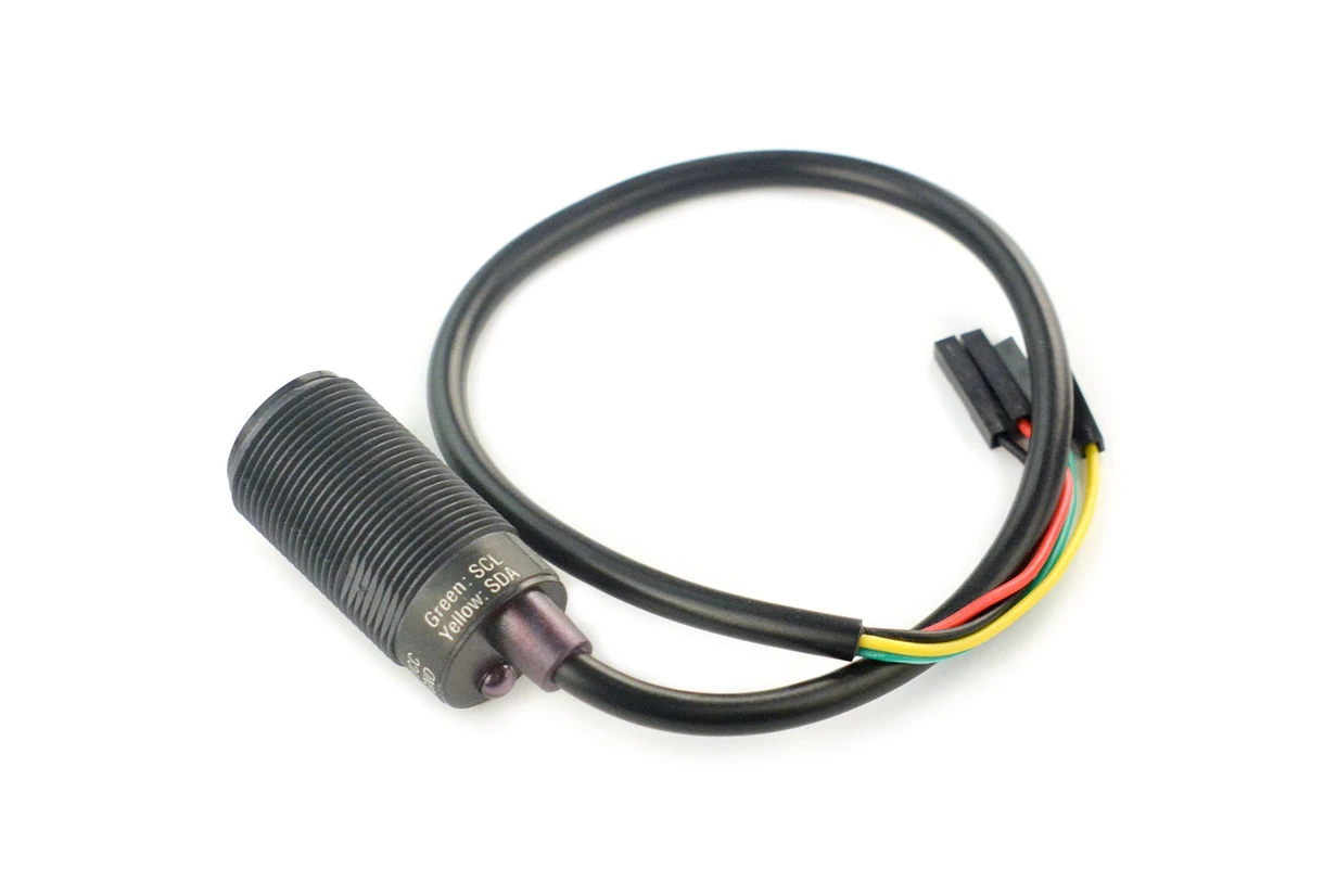
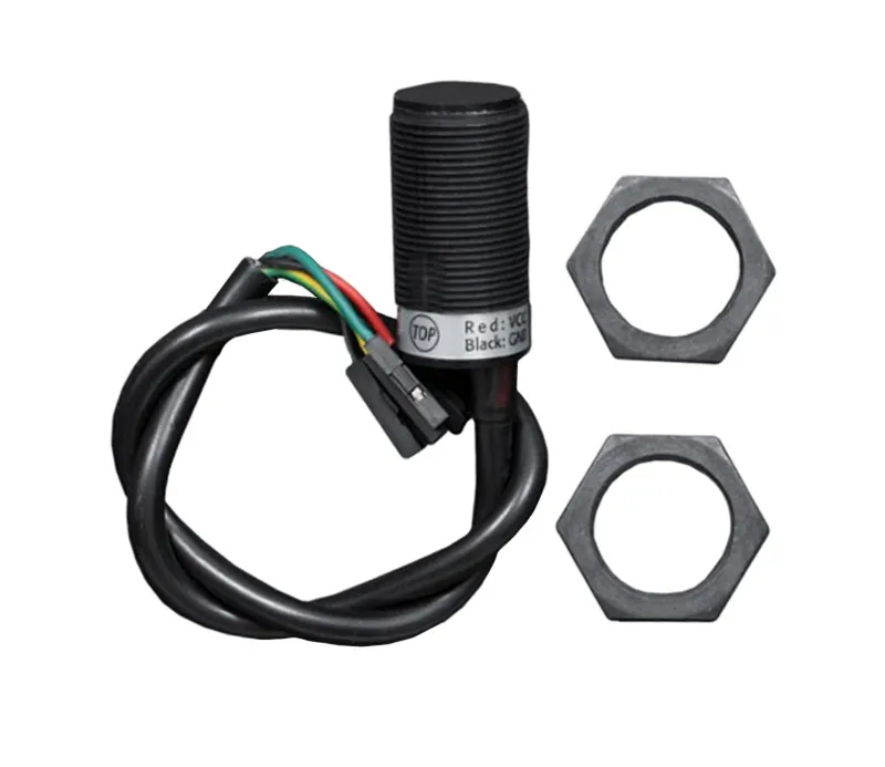
The module communicates through the I2C interface and requires only four wires for operation: power, ground, SDA, and SCL. This simple connection makes it easy to integrate with Arduino boards and other microcontrollers that support I2C communication. The compact size and high sensitivity of the sensor make it suitable for robotics, automation, security systems, and educational electronics projects.
Features
- Tracks up to four infrared objects simultaneously
- Can be used for robot navigation using infrared transmitters
- Functions as a flame sensor to detect heat sources and flame positions
- Simple four wire connection using I2C communication
- Compact design for easy integration into electronic projects
- High sensitivity and accurate infrared signal detection
- Adjustable detection range for different applications
- Compatible with Arduino microcontrollers and other I2C enabled devices
- Suitable for robotics, automation, and security system applications
Specifications
- Operating voltage: 3.3V to 5V
- Interface: I2C
- Detecting distance: 0 to 3 meters
- Horizontal detecting angle: 33 degrees
- Vertical detecting angle: 23 degrees
- Resolution: 128 x 96 pixels
- Object tracking: up to 4 infrared sources
- Dimensions: 32 mm x 16 mm
Applications
- Robot navigation using infrared transmitters
- Light barrier systems for direction detection
- Flame detection and fire monitoring systems
- Infrared object tracking and positioning
- Robotics and automation projects
Pin Connections

| Wire Color | Connection |
|---|---|
| Red | VCC |
| Yellow | SDA |
| Green | SCL |
| Black | GND |
Sample Project
When the camera detects an infrared signal, it displays the coordinates of the detected object. The first detected object will appear in the first coordinate position. If additional objects are detected, they will be listed in order of detection. If an object moves out of view, its position will return a value of 1023,1023. The sensor supports tracking up to four infrared objects at the same time.
Arduino Sample Code
#include "Wire.h"
int IRsensorAddress = 0xB0;
int slaveAddress;
int ledPin = 13;
boolean ledState = false;
byte data_buf[16];
int i;
int Ix[4];
int Iy[4];
int s;
void Write_2bytes(byte d1, byte d2) {
Wire.beginTransmission(slaveAddress);
Wire.write(d1);
Wire.write(d2);
Wire.endTransmission();
}
void setup() {
slaveAddress = IRsensorAddress >> 1;
Serial.begin(19200);
pinMode(ledPin, OUTPUT);
Wire.begin();
Write_2bytes(0x30, 0x01);
delay(10);
Write_2bytes(0x30, 0x08);
delay(10);
Write_2bytes(0x06, 0x90);
delay(10);
Write_2bytes(0x08, 0xC0);
delay(10);
Write_2bytes(0x1A, 0x40);
delay(10);
Write_2bytes(0x33, 0x33);
delay(10);
delay(100);
}
void loop() {
ledState = !ledState;
digitalWrite(ledPin, ledState);
Wire.beginTransmission(slaveAddress);
Wire.write(0x36);
Wire.endTransmission();
Wire.requestFrom(slaveAddress, 16);
for (i = 0; i < 16; i++) {
data_buf[i] = 0;
}
i = 0;
while (Wire.available() && i < 16) {
data_buf[i] = Wire.read();
i++;
}
Ix[0] = data_buf[1];
Iy[0] = data_buf[2];
s = data_buf[3];
Ix[0] += (s & 0x30) << 4;
Iy[0] += (s & 0xC0) << 2;
Ix[1] = data_buf[4];
Iy[1] = data_buf[5];
s = data_buf[6];
Ix[1] += (s & 0x30) << 4;
Iy[1] += (s & 0xC0) << 2;
Ix[2] = data_buf[7];
Iy[2] = data_buf[8];
s = data_buf[9];
Ix[2] += (s & 0x30) << 4;
Iy[2] += (s & 0xC0) << 2;
Ix[3] = data_buf[10];
Iy[3] = data_buf[11];
s = data_buf[12];
Ix[3] += (s & 0x30) << 4;
Iy[3] += (s & 0xC0) << 2;
for (i = 0; i < 4; i++) {
Serial.print(Ix[i]);
Serial.print(",");
Serial.print(Iy[i]);
if (i < 3) Serial.print(",");
}
Serial.println("");
delay(15);
}
In addition to infrared tracking, the module can also function as a flame sensor. It can detect heat sources and determine the position of a flame within its field of view, making it useful for fire alarm systems, safety monitoring, and automated fire detection projects.
The module communicates through the I2C interface and requires only four wires for operation: power, ground, SDA, and SCL. This simple connection makes it easy to integrate with Arduino boards and other microcontrollers that support I2C communication. The compact size and high sensitivity of the sensor make it suitable for robotics, automation, security systems, and educational electronics projects.
Features
- Tracks up to four infrared objects simultaneously
- Can be used for robot navigation using infrared transmitters
- Functions as a flame sensor to detect heat sources and flame positions
- Simple four wire connection using I2C communication
- Compact design for easy integration into electronic projects
- High sensitivity and accurate infrared signal detection
- Adjustable detection range for different applications
- Compatible with Arduino microcontrollers and other I2C enabled devices
- Suitable for robotics, automation, and security system applications
Specifications
- Operating voltage: 3.3V to 5V
- Interface: I2C
- Detecting distance: 0 to 3 meters
- Horizontal detecting angle: 33 degrees
- Vertical detecting angle: 23 degrees
- Resolution: 128 x 96 pixels
- Object tracking: up to 4 infrared sources
- Dimensions: 32 mm x 16 mm
Applications
- Robot navigation using infrared transmitters
- Light barrier systems for direction detection
- Flame detection and fire monitoring systems
- Infrared object tracking and positioning
- Robotics and automation projects
Pin Connections
| Wire Color | Connection |
|---|---|
| Red | VCC |
| Yellow | SDA |
| Green | SCL |
| Black | GND |
Sample Project
When the camera detects an infrared signal, it displays the coordinates of the detected object. The first detected object will appear in the first coordinate position. If additional objects are detected, they will be listed in order of detection. If an object moves out of view, its position will return a value of 1023,1023. The sensor supports tracking up to four infrared objects at the same time.
Arduino Sample Code
#include "Wire.h"
int IRsensorAddress = 0xB0;
int slaveAddress;
int ledPin = 13;
boolean ledState = false;
byte data_buf[16];
int i;
int Ix[4];
int Iy[4];
int s;
void Write_2bytes(byte d1, byte d2) {
Wire.beginTransmission(slaveAddress);
Wire.write(d1);
Wire.write(d2);
Wire.endTransmission();
}
void setup() {
slaveAddress = IRsensorAddress >> 1;
Serial.begin(19200);
pinMode(ledPin, OUTPUT);
Wire.begin();
Write_2bytes(0x30, 0x01);
delay(10);
Write_2bytes(0x30, 0x08);
delay(10);
Write_2bytes(0x06, 0x90);
delay(10);
Write_2bytes(0x08, 0xC0);
delay(10);
Write_2bytes(0x1A, 0x40);
delay(10);
Write_2bytes(0x33, 0x33);
delay(10);
delay(100);
}
void loop() {
ledState = !ledState;
digitalWrite(ledPin, ledState);
Wire.beginTransmission(slaveAddress);
Wire.write(0x36);
Wire.endTransmission();
Wire.requestFrom(slaveAddress, 16);
for (i = 0; i < 16; i++) {
data_buf[i] = 0;
}
i = 0;
while (Wire.available() && i < 16) {
data_buf[i] = Wire.read();
i++;
}
Ix[0] = data_buf[1];
Iy[0] = data_buf[2];
s = data_buf[3];
Ix[0] += (s & 0x30) << 4;
Iy[0] += (s & 0xC0) << 2;
Ix[1] = data_buf[4];
Iy[1] = data_buf[5];
s = data_buf[6];
Ix[1] += (s & 0x30) << 4;
Iy[1] += (s & 0xC0) << 2;
Ix[2] = data_buf[7];
Iy[2] = data_buf[8];
s = data_buf[9];
Ix[2] += (s & 0x30) << 4;
Iy[2] += (s & 0xC0) << 2;
Ix[3] = data_buf[10];
Iy[3] = data_buf[11];
s = data_buf[12];
Ix[3] += (s & 0x30) << 4;
Iy[3] += (s & 0xC0) << 2;
for (i = 0; i < 4; i++) {
Serial.print(Ix[i]);
Serial.print(",");
Serial.print(Iy[i]);
if (i < 3) Serial.print(",");
}
Serial.println("");
delay(15);
}