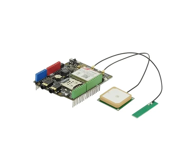
The shield includes an onboard microphone and a 3.5 mm headphone jack which simplifies audio communication projects and reduces the need for additional components. External GSM and GPS antennas can also be connected using the onboard antenna connectors to improve signal reception and positioning accuracy.
The SIM808 GPS GPRS GSM Arduino Shield V1.0 uses the latest version of the SIMCOM SIM808 module. Compared with early SIM808 modules available on the market, the newer module provides improved reliability and system stability. However, some GPS related AT commands are not compatible with older versions of the SIM808 module, therefore users should refer to the updated AT command documentation when developing applications.
Features
- Integrated GSM GPRS communication and GPS positioning module.
- Compatible with Arduino UNO, Leonardo, Mega, and other Arduino boards.
- Supports SMS messaging and voice call functions.
- Supports MMS, DTMF, FTP, and GPRS data communication.
- Built in GPS receiver for location tracking and navigation.
- Onboard microphone and 3.5 mm headphone jack for audio communication.
- External antenna connectors for GSM and GPS antennas.
- LED indicators for power, network status, and operation modes.
- AT command control based on GSM standards.
- Improved stability compared to earlier SIM808 modules.
Specifications
- Operating Voltage: 5V
- Input Power: 7V to 23V
- GSM Frequency Bands: 850 MHz, 900 MHz, 1800 MHz, 1900 MHz
- GPRS Multi Slot Class: Class 12 and Class 10
- GPRS Mobile Station Class: Class B
- GSM Compliance: GSM phase 2 and phase 2 plus
- Transmission Power: Class 4 at 850 and 900 MHz
- Transmission Power: Class 1 at 1800 and 1900 MHz
- Low Power Consumption Mode: 100 mA at 7V in GSM mode
- Control Interface: AT commands compliant with 3GPP TS 27.007 and 27.005
- GPS Support: Integrated satellite navigation technology
- Status Indicators: Power indicator, network status indicator, operating mode indicator
- Operating Temperature: -40 C to 85 C
- Board Size: 69 mm x 54 mm
Pinout of the SIM808 Shield

Pin and Hardware Notes
- Occupied pins include D0, D1, and D12. Digital pin D12 is connected to the SIM808 module power GPIO and can be used for module on or off control.
- The onboard microphone and the external 3.5 mm microphone share the same microphone channel. When an external microphone is connected, the onboard microphone is automatically disconnected.
- The boot switch button controls the SIM808 module power. Press for 1 second to start the module and press for 3 seconds to turn it off.
- The ON LED indicates SIM808 power status and lights when the module is powered.
- The NET LED indicates GSM network status. Fast flashing means searching for network, slow flashing every 3 seconds means network registration completed.
- The function switch selects the communication mode.
- None position allows sketch uploading to the Arduino.
- USB debug mode allows the SIM808 module to communicate directly with a computer for AT command debugging.
- Arduino mode allows the SIM808 module to communicate with the Arduino board.
Arduino Example Code
Install the library from :
#include "DFRobot_SIM808.h"

#define PHONE_NUMBER "187******39"

DFRobot_SIM808 sim808(&Serial);

void setup()
{
  Serial.begin(9600);

  while(!sim808.init())
  {
    delay(1000);
    Serial.print("Sim808 init error");
  }

  Serial.println("Sim808 init success");
  Serial.println("Start to call");

  sim808.callUp(PHONE_NUMBER);
}

void loop()
{
}
Resources:
The shield includes an onboard microphone and a 3.5 mm headphone jack which simplifies audio communication projects and reduces the need for additional components. External GSM and GPS antennas can also be connected using the onboard antenna connectors to improve signal reception and positioning accuracy.
The SIM808 GPS GPRS GSM Arduino Shield V1.0 uses the latest version of the SIMCOM SIM808 module. Compared with early SIM808 modules available on the market, the newer module provides improved reliability and system stability. However, some GPS related AT commands are not compatible with older versions of the SIM808 module, therefore users should refer to the updated AT command documentation when developing applications.
Features
- Integrated GSM GPRS communication and GPS positioning module.
- Compatible with Arduino UNO, Leonardo, Mega, and other Arduino boards.
- Supports SMS messaging and voice call functions.
- Supports MMS, DTMF, FTP, and GPRS data communication.
- Built in GPS receiver for location tracking and navigation.
- Onboard microphone and 3.5 mm headphone jack for audio communication.
- External antenna connectors for GSM and GPS antennas.
- LED indicators for power, network status, and operation modes.
- AT command control based on GSM standards.
- Improved stability compared to earlier SIM808 modules.
Specifications
- Operating Voltage: 5V
- Input Power: 7V to 23V
- GSM Frequency Bands: 850 MHz, 900 MHz, 1800 MHz, 1900 MHz
- GPRS Multi Slot Class: Class 12 and Class 10
- GPRS Mobile Station Class: Class B
- GSM Compliance: GSM phase 2 and phase 2 plus
- Transmission Power: Class 4 at 850 and 900 MHz
- Transmission Power: Class 1 at 1800 and 1900 MHz
- Low Power Consumption Mode: 100 mA at 7V in GSM mode
- Control Interface: AT commands compliant with 3GPP TS 27.007 and 27.005
- GPS Support: Integrated satellite navigation technology
- Status Indicators: Power indicator, network status indicator, operating mode indicator
- Operating Temperature: -40 C to 85 C
- Board Size: 69 mm x 54 mm
Pinout of the SIM808 Shield
Pin and Hardware Notes
- Occupied pins include D0, D1, and D12. Digital pin D12 is connected to the SIM808 module power GPIO and can be used for module on or off control.
- The onboard microphone and the external 3.5 mm microphone share the same microphone channel. When an external microphone is connected, the onboard microphone is automatically disconnected.
- The boot switch button controls the SIM808 module power. Press for 1 second to start the module and press for 3 seconds to turn it off.
- The ON LED indicates SIM808 power status and lights when the module is powered.
- The NET LED indicates GSM network status. Fast flashing means searching for network, slow flashing every 3 seconds means network registration completed.
- The function switch selects the communication mode.
- None position allows sketch uploading to the Arduino.
- USB debug mode allows the SIM808 module to communicate directly with a computer for AT command debugging.
- Arduino mode allows the SIM808 module to communicate with the Arduino board.
Arduino Example Code
Install the library from :
#include "DFRobot_SIM808.h"

#define PHONE_NUMBER "187******39"

DFRobot_SIM808 sim808(&Serial);

void setup()
{
  Serial.begin(9600);

  while(!sim808.init())
  {
    delay(1000);
    Serial.print("Sim808 init error");
  }

  Serial.println("Sim808 init success");
  Serial.println("Start to call");

  sim808.callUp(PHONE_NUMBER);
}

void loop()
{
}
Resources: