Force-Sensitive RP-C7.6-LT Thin Film Pressure Sensor DFRobot - SEN-0298
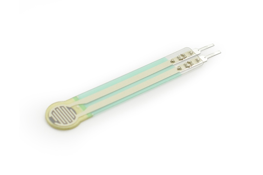
The RP-C7.6-LT thin film pressure sensor is highly flexible and easy to use. Peel off the protection cover and stick the sensor on the surface to detect pressure. The sensor records the intensity and frequency of force, making it suitable for applications such as pressure switches, bed monitoring systems, intelligent sneakers, and medical devices.
Package Includes:
1 x RP-C7.6-LT thin film pressure sensor
The sensor consists of an ultra-thin film with excellent mechanical properties, conductive materials, and nanometer pressure-sensitive layers. The upper layer contains a thin film and pressure-sensitive layer, while the lower layer contains a thin film and conductive circuit. Both layers are glued together with double-sided tape. When pressure is applied to the active area, the disconnected circuit of the lower layer is connected through the pressure-sensitive layer of the upper layer, converting pressure into resistance. The output resistance decreases as pressure increases. The sensor is durable and designed to detect both static and dynamic pressure with high response speed.
Specification
- Thickness: 0.3mm
- Trigger Force: 30g, trigger when default resistance <200k ohms
- Pressure Measuring Range: 30g to 1.5kg
- Static and Dynamic Pressure Measurement:
- Initial Resistance: greater than 10 megohms
- Activation Time: less than 0.01 seconds
- Operating Temperature: -40 to 85 degrees Celsius
- Lifespan: greater than 1 million cycles
- Hysteresis: plus or minus 10 percent, 1000 gram force
- Response Time: less than 10 milliseconds
- EMI: not generated
- EDS: not generated
- Drift: less than 5 percent under 1 kilogram force for 24 hours static load
Tutorial
This tutorial demonstrates how to use the RP-C7.6-LT sensor with an Arduino UNO board and observe serial output changes under different pressure conditions.
Requirements
- Hardware:
- Arduino UNO x1
- RP-C7.6-LT Thin Film Pressure Sensor x1
- Computer x1
- Dupont wires
- Software:
- Arduino IDE
Resistance vs Force
- Abscissa: force in grams
- Ordinate: resistance in ohms
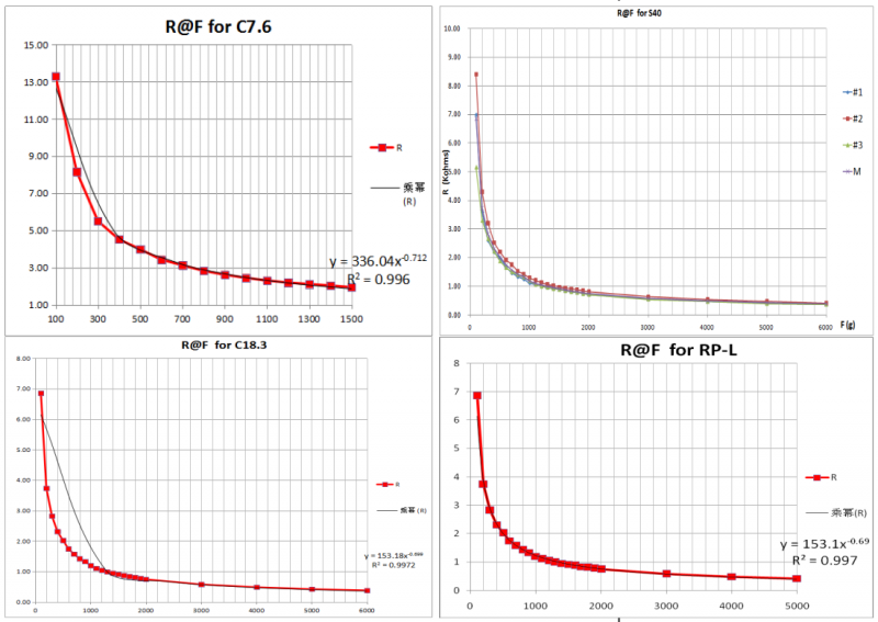
When pressure is applied to the sensor, the lower layer circuit connects through the pressure-sensitive layer of the upper layer, converting pressure into resistance. Output resistance decreases as force increases. The sensor outputs different resistances for different forces. The graph above shows this relationship. If the applied force is too strong or too weak, the slope is too large or small. The sensor is better suited for qualitative measurements. Using it for quantitative measurements may result in large errors.
- R@F for C7.6: SEN0297, SEN0298
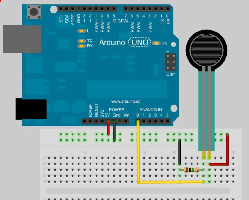
Connection Diagram
Sample Code
/***************************************************
 * Piezo Vibration Sensor
 ****************************************************
 * This example: The sensors detect vibration
 * @author linfeng([email protected])
 * @version V1.0
 * @date 2016-2-26
 * GNU Lesser General Public License.
 * All above must be included in any redistribution
 ****************************************************/
#define sensorPin A0

void setup() {
Serial.begin(115200);
}

void loop() {
int x = analogRead(sensorPin);
Serial.println(x);
delay(50);
}
Expected Results
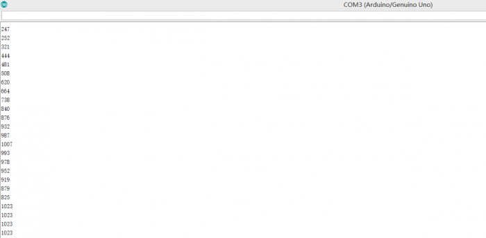
The serial output changes as shown when the sensor is pressed. The serial data decreases linearly as the force increases. It is recommended to use the sensor for qualitative measurements.
The sensor consists of an ultra-thin film with excellent mechanical properties, conductive materials, and nanometer pressure-sensitive layers. The upper layer contains a thin film and pressure-sensitive layer, while the lower layer contains a thin film and conductive circuit. Both layers are glued together with double-sided tape. When pressure is applied to the active area, the disconnected circuit of the lower layer is connected through the pressure-sensitive layer of the upper layer, converting pressure into resistance. The output resistance decreases as pressure increases. The sensor is durable and designed to detect both static and dynamic pressure with high response speed.
Specification
- Thickness: 0.3mm
- Trigger Force: 30g, trigger when default resistance <200k ohms
- Pressure Measuring Range: 30g to 1.5kg
- Static and Dynamic Pressure Measurement:
- Initial Resistance: greater than 10 megohms
- Activation Time: less than 0.01 seconds
- Operating Temperature: -40 to 85 degrees Celsius
- Lifespan: greater than 1 million cycles
- Hysteresis: plus or minus 10 percent, 1000 gram force
- Response Time: less than 10 milliseconds
- EMI: not generated
- EDS: not generated
- Drift: less than 5 percent under 1 kilogram force for 24 hours static load
Tutorial
This tutorial demonstrates how to use the RP-C7.6-LT sensor with an Arduino UNO board and observe serial output changes under different pressure conditions.
Requirements
- Hardware:
- Arduino UNO x1
- RP-C7.6-LT Thin Film Pressure Sensor x1
- Computer x1
- Dupont wires
- Software:
- Arduino IDE
Resistance vs Force
- Abscissa: force in grams
- Ordinate: resistance in ohms
When pressure is applied to the sensor, the lower layer circuit connects through the pressure-sensitive layer of the upper layer, converting pressure into resistance. Output resistance decreases as force increases. The sensor outputs different resistances for different forces. The graph above shows this relationship. If the applied force is too strong or too weak, the slope is too large or small. The sensor is better suited for qualitative measurements. Using it for quantitative measurements may result in large errors.
- R@F for C7.6: SEN0297, SEN0298
Connection Diagram
Sample Code
/***************************************************
 * Piezo Vibration Sensor
 ****************************************************
 * This example: The sensors detect vibration
 * @author linfeng([email protected])
 * @version V1.0
 * @date 2016-2-26
 * GNU Lesser General Public License.
 * All above must be included in any redistribution
 ****************************************************/
#define sensorPin A0

void setup() {
Serial.begin(115200);
}

void loop() {
int x = analogRead(sensorPin);
Serial.println(x);
delay(50);
}
Expected Results
The serial output changes as shown when the sensor is pressed. The serial data decreases linearly as the force increases. It is recommended to use the sensor for qualitative measurements.